Amiga 500 Mainboard

#ZX Spectrum

R Tape loading error

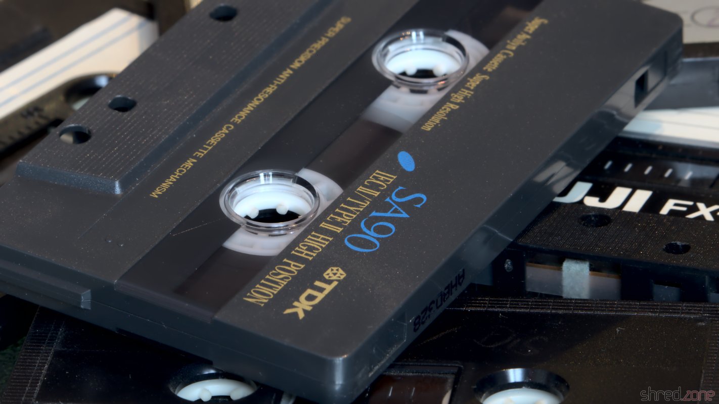
In the early time of home computers, at the beginning of the 1980's, hard disks and even floppy disks were too expensive for home use. The cheapest way for storing large amounts of data was the cassette tape. Cassettes and tape recorders were affordable and available in almost any household.

In this blog article, I'm going to explain how the Sinclair ZX Spectrum stored programs on cassette tapes. Other home computers of that time, like the Commodore 64 or Amstrad CPC, worked in a similar fashion.

Cassette tapes were designed to store audio signals like voice or music, so the inventors of the home computers had to find a way to convert data to audio signals. The easiest way is to serialize the data to a bit stream of 1's and 0's, and generate a long rectangular wave cycle for "1" and a short rectangular wave cycle for "0". This is what the ZX Spectrum actually does!

A short wave cycle is generated by giving power to the audio output for 855 so called T-states, and then turning off the power for another 855 T-states. A "T-state" is the time of a single clock pulse of the Z80-A CPU. As the CPU of a classic ZX Spectrum is clocked with 3.5 MHz, a T-state has a duration of 286 ns. The duration of a short wave cycle is thus 489 µs, giving an audio frequency of about 2,045 Hz. The long wave cycle is just twice as long.

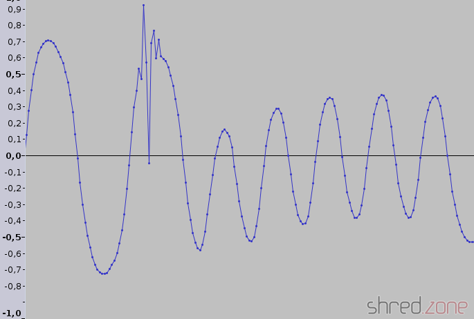
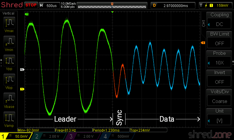
Due to all kind of filters in the analog audio path, the rectangular signal is smoothed to a sinusoidal signal when played back. A Schmitt trigger inside the ZX Spectrum's hardware converts the audio signal back to a rectangular shape. Since the audio signal can have different amplitudes or could even be inverted, the hardware only cares for signal edges, not for levels. All that the loader routine now has to do is to measure the duration of the pulses, regenerate the bit stream, and put the bytes back together.

If you think that things cannot be that easy, you are right. 😄 The most difficult part for the loader is to find the start of the bit stream. If it is off by only one cycle (or even just a pulse), all the bytes are shifted by one bit, and the result is useless. All kind of noise on the tape makes it impossible to just wait for the signal to start, though.

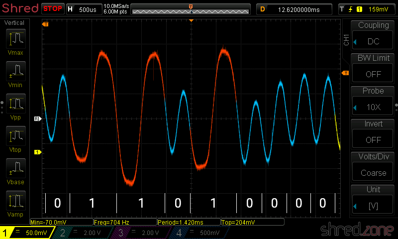
For this reason, the recording starts with a leader signal, followed by a sync wave cycle, followed by the bit stream itself. The leader signal is just a continuous wave with a pulse length of 2,168 T-states, giving an 806 Hz tone that is displayed by red and cyan border colors on the TV. The sync wave cycle is a pulse of 667 T-States "on", followed by 735 T-states "off". After that, the actual data stream begins, which is displayed in blue and yellow border colors. When the last bit was transmitted, the data stream just ends.

So when the ZX Spectrum loads a file from tape, it first waits for the 806 Hz leader signal. If it was detected for at least 317 ms, it waits for the sync pulses, then it starts reading the bit sequence until there is a timeout while waiting for the next pulse.

It is a very simple way to store data on tape. And still, it is surprisingly reliable. After 30 years, I could recover almost all files from my old cassette tapes. Some of them were of the cheapest brands I could get my hands on back in 1987.

The only disadvantage is that this method is very slow. With 489 µs for a "0" and 978 µs for a "1", saving just 48 KBytes of data can take up to 6 minutes, giving an average bit rate of 1,363 bps (yes, bits per second). If we were to save a single 3 MBytes mp3 file that way, it would take almost 5 hours (and 5 cassettes with 60 minutes recording time each).

Some commercial games used speed loaders and copy protections. Speed loaders just reduced the number of T-states for the pulses, which increased the bit rate. Some copy protections used a "clicking" leader tone, where the leader signal was interrupted before the minimal detection time of 317 ms was reached. The original loader routine could not synchronize to these kind of signals, so it was impossible to read those files into copy programs. Those protection measures could still be circumvented by copying directly from tape to tape, but this only worked a few times due to increasing audio noise.

In the next article, I will take a deeper look at the bit stream contents, and I will also explain where the dreaded "R Tape loading error" comes from.

Z80 Disassembler

Some days ago, I was adding a Z80 disassembler to my tzxtools. I could not find one for Python, so I decided to write my own. The result fits into a single Python source file. This article is the Making-of…

The Zilog Z80 is an 8 bit processor. This means that (almost) all instructions only consume 1 byte. For example, the instruction ret (return from subroutine) has C9 as byte representation. Some commands are followed by another byte (as a constant to be used, or a relative jump displacement) or another two bytes (as a 16 bit constant or absolute address). Some examples:

C9------retReturn from subroutine
3E23----ld a,$23Load constant $23 into A register
C33412--jp $1234Jump to address $1234

Note that for 16 bit constants, the bytes seem to be reversed in memory. This is because the Z80 is a so-called little endian CPU, where the lower byte comes first. Some other processor families (like the 68000 ) are big endian and store the higher word first.

So there are 256 instructions only, which makes it pretty easy to disassemble them. I used an array of 256 entries, where each entry contains the instruction of the respective byte as a string. For constants, I have used placeholders like "##" or "$". If such a placeholder is found in the instruction string after decoding, the appropriate number of bytes are fetched, and the placeholder is replaced by the value that was found.

If we were to write a disassembler for the 8080 CPU, we were done now. However, the Z80 has some extensions that need to be covered, namely two extended instruction sets and two index registers.

One set of extended instructions is selected by an $ED prefix, and contains rarely used instructions. The other instruction set is selected by a $CB prefix and has bit manipulation and some rotation instructions.

EDB0----ldirCopy BC bytes from HL to DE
ED4B7856ld bc,($5678)Loads value from address $5678 into BC register pair
CBC7----set 0,aSet bit 0 in A register

For the $ED prefix, I used a separate array for decoding the instructions. The $CB instructions follow a simple bit scheme, so the instructions could be decoded by a few lines of Python code.

The Z80 provides two index registers, called IX and IY. They are used when the instruction is prefixed with a $DD or $FD byte, respectively. These prefixes basically use the selected index register instead of the HL register pair for the current instruction. However, if the (HL) addressing mode is used, an additional byte sized offset is provided. The index registers can be combined with the $CB prefix, which can make things complicated.

E5------push hlPush HL to stack
DDE5----push ixPush IX to stack (same opcode E5, but now with DD prefix)
FDE5----push iyPush IY to stack (now with FD prefix)
FD2180FFld iy,$FF80Load $FF80 constant into IY register
DD7E09--ld a,(ix+9)Load value at address IX+9 to A register (offset is after opcode)
CBC6----set 0,(hl)Set bit 0 at address in HL
FDCB03C6set 0,(iy+3)Set bit 0 at address IY+3 (offset is before opcode)

When the disassembler detects a $DD or $FD prefix, it sets a respective ix or iy flag. Later, when the instruction is decoded, every occurance of HL is replaced by either IX or IY. If (HL) was found, another byte is fetched from the byte stream and used as index offset for (IX+dd) or (IY+dd).

There is one exception. The examples above show that the index offset is always found at the third byte. This means that when the index register is combined with a $CB prefix, the actual instruction is located after the index. This is a case that needed special treatment in my disassembler. If this combination is detected, then the index offset is fetched and stored before the instruction is decoded.

Phew, this was complicated. Now we’re able to disassemble the official instruction set of the Z80 CPU. But we’re not done yet. There are a number of undocumented instructions. The manufacturer Zilog never documented them, they are not quite useful, but they still work on almost any Z80 CPU and are actually in use.

Most of them are covered just by extending the instruction arrays. Additionally, the $DD or $FD prefixes do not only affect the HL register pair, but also just the H and L registers, giving IXH/IYH and IXL/IYL registers. This is covered by the instruction post processing. A very special case is the $CB prefix in combination with index registers, giving a whole bunch of new instructions that store the result of a bit operation in another register. This actually needed special treatment by a separate $CB prefix instruction decoder.

Finally, the ZX Spectrum Next is going to bring some new instructions like multiplication or ZX Spectrum hardware related stuff. They were again covered by extending the instruction arrays. The only exceptions are the push [const] instruction where the constant is stored as big endian, and the nextreg [reg],[val] instruction that is (as the only instruction) followed by two constants.

And that’s it. 😄 This is how to write a Z80 disassembler in a single afternoon.

Recovering old ZX Spectrum tapes, Part 2

The ZX Spectrum was a comparable cheap home computer, and thus the tape loading and saving mechanisms have not been very sophisticated. The tape recording is just a stream of short waves (0 bit) and long waves (1 bit). The stream starts with a leader signal (a series of even longer waves) and a single sync pulse. So, in the theory, reading a tape recording means measuring single wave lengths, by taking the time between two zero-crossings, and converting them into a sequence of bytes.

But then again, we are dealing with 1980's analog technique. In practice, we will find signals like this. A click produced an additional zero-crossing that is to be ignored. Also, the amplitudes and DC offsets change all the time.

And pooof... There went another week of nightly hacking Python code, having very close looks at audio waves, and searching for clues about why tzxwav won't behave like I expect it to behave. But I think the result is worth looking at now! tzxwav now reads almost all of my tape samples without those dreaded CRC errors. If there are CRC errors, the sample was usually so damaged that it would need manual restauration.

And as a bonus, it is now almost twice as slow as before. 🤭 But speed was never a goal anyway, as people are likely to convert their old tapes only once.

Recovering old ZX Spectrum tapes

The author, on Christmas Eve 1985 Since I am in the mood of heavy ZX Spectrum retro action, I dug out all my old computer tapes in an attept to digitize and convert them. It turned out to be more difficult than I thought...

The first trouble was to find a tape player. I had disposed my last tape recorder a couple of years ago. The new ones I found at Amazon looked nice on the first sight. They could be connected to the USB port or even digitize the tapes straight to an USB stick. The customer reviews were scaring off: cheap plastic, poor sound, digitizing to USB stick was only possible on battery power... I had more luck on eBay, where I found a genuine 1990’s Aiwa Walkman (it’s even a recorder, with auto reverse and Dolby NR) in good condition for about the same price.

I connected the Walkman to my computer’s microphone input using a cable with 3.5mm stereo jacks, selected the correct tape type (Normal or CrO2), and turned off Dolby NR. Then I digitized right away, using Audacity for recording and post processing. I used 16 bits per channel, and a 44100 Hz sampling rate. The ZX Spectrum provided a mono signal, so I chose the left or right channel (depending on the quality) and discarded the other one. Mixing down the stereo signal turned out to be problematic, as well as using a lossy file format like ogg.

The WAV files can be loaded into the Fuse Emulator, but it’s better to convert them to TZX files, as they are much smaller. There are a few tools for that, for example audio2tape that comes with Fuse. I wasn’t satisified with the result though, as the generated TZX files contained many CRC errors. MakeTZX is also worth a try, as it supports digital filters, but I was unable to make it run on Linux. Some other converter tools are for Windows only, and thus not very interesting. 😉

So I found myself writing a set of TZX tools in Python. It contains tzxwav, that’s yet another tool for converting WAV files to TZX files, but is robust against poor audio quality. It took me three weeks of work, and about 30 hours of tape material, until it was able to successfully read almost all of my tape recordings.

An advantage of TZX files is that they contain the raw ZX Spectrum binaries, so they are very easy to extract. tzxcat allows to retrieve single binaries from TZX files, which can then be converted into PNG files, BASIC sources or whatever, provided there are converters for it.

What I have now are TZX files of all my old ZX Spectrum tapes. It was very interesting to rediscover my old files, screens, programs and source codes. In 1987 and 1988, I wrote a lot of more or less useful tools, designed several fonts and completed two demos.

Optimizations

On a slow processor like the Z80, it is essential to think about execution time. Often a clean approach is too slow, and you need to optimize the code to make it a lot faster.

The ZX Spectrum screen bitmap is not linear. The 192 pixel rows are divided into three sections of 64 pixel rows. In each of these sections, all the 8 first pixel rows come first, followed by the second pixel rows, and so on. The advantage is that when writing characters to the bitmap, you only need to increment the H register to reach the next bitmap row. The disadvantage is that a pixel precise address calculation is hell.

This is how the coordinates of a pixel are mapped to the address:

HL
1514131211109876543210
010Y7Y6Y2Y1Y0Y5Y4Y3X7X6X5X4X3

X2, X1 and X0 represent the bit number at the address. It can be used as a counter for right shift operations.

My first attempt was a straightforward code that shifted, masked and moved the bit groups into the correct places. It took 117 cycles. This is nice, but we can do better.

We need a lot of rotation operations to shift the bits to the right position. Rotation is a rather expensive operation on a Z80, because there are no instructions that rotate by more than one bit at a time. My idea was to divide the X coordinate by 8 (by rotating it three times to the right) and simultaneously shift Y3 to Y5 into the L register. With a similar trick, I could set bit 14 while rotating, which saved me another or operation with a constant.

This is the final optimized code. It takes the X coordinate in the C register, and the Y coordinate in the B register. The screen address is returned in the HL register pair. BC and DE are unchanged, so there is no need for expensive push and pop operations.

pixelAddress:   ld      a, b
                and     %00000111
                ld      h, a    ; h contains Y2-Y0
                ld      a, b
                rra
                scf             ; set bit 14
                rra
                rra
                ld      l, a    ; l contains Y5-Y3
                and     %01011000
                or      h
                ld      h, a    ; h is complete now
                ld      a, c    ; divide X by 8
                rr      l       ; and rotate Y5-Y3 in
                rra
                rr      l
                rra
                rr      l
                rra
                ld      l, a    ; l is complete now
                ret

It only takes 108 cycles, ret inclusive. Optimizing saved me 9 cycles (or about 8%). This doesn’t sound like much, but if the code is invoked in a loop, those 9 cycles are multiplied by the number of loop iterations.

I claim this is the fastest solution without resorting to a lookup table. Try to beat me! 😁