Clockwork

#ZX Spectrum

A new Harlequin

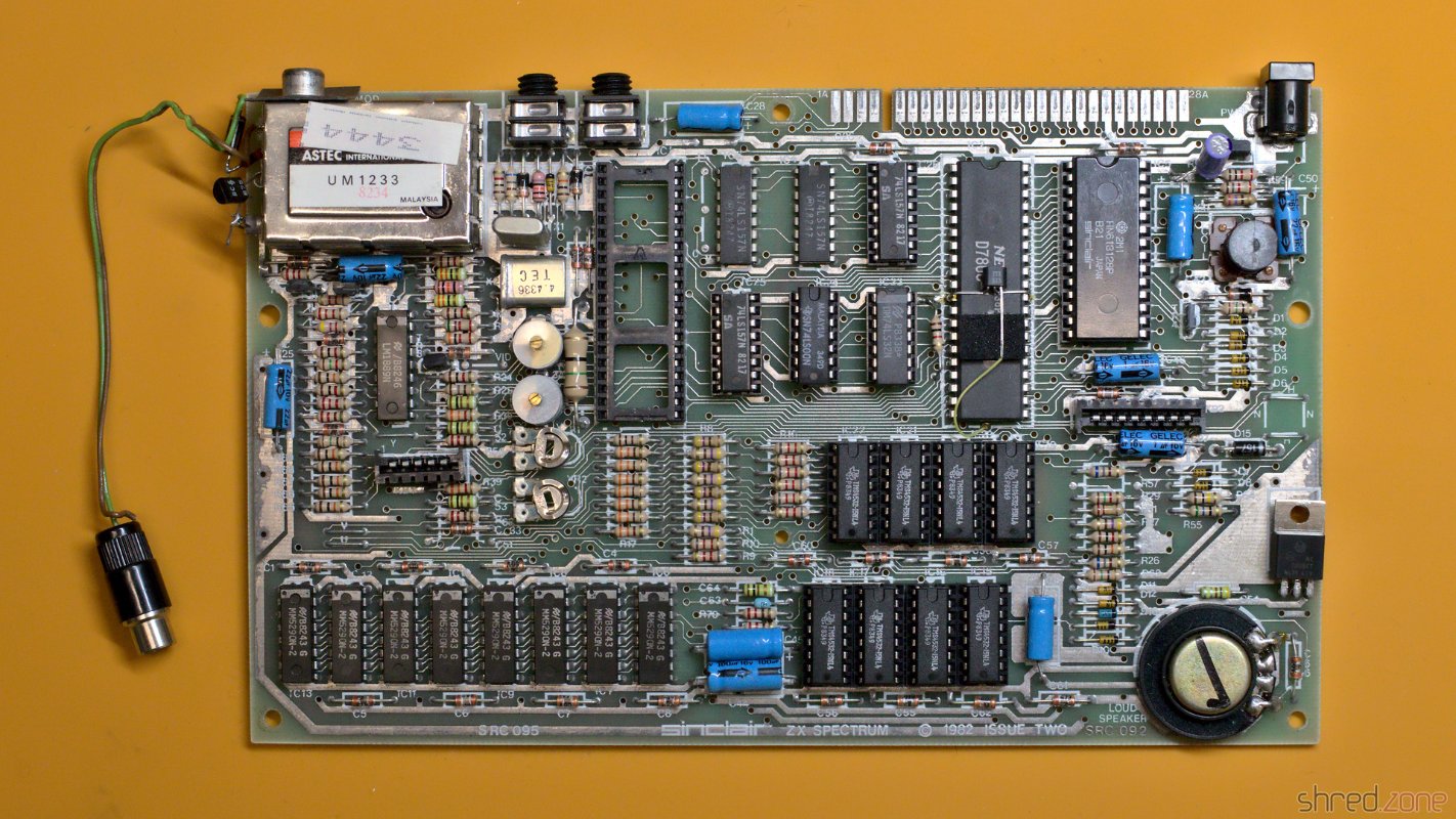
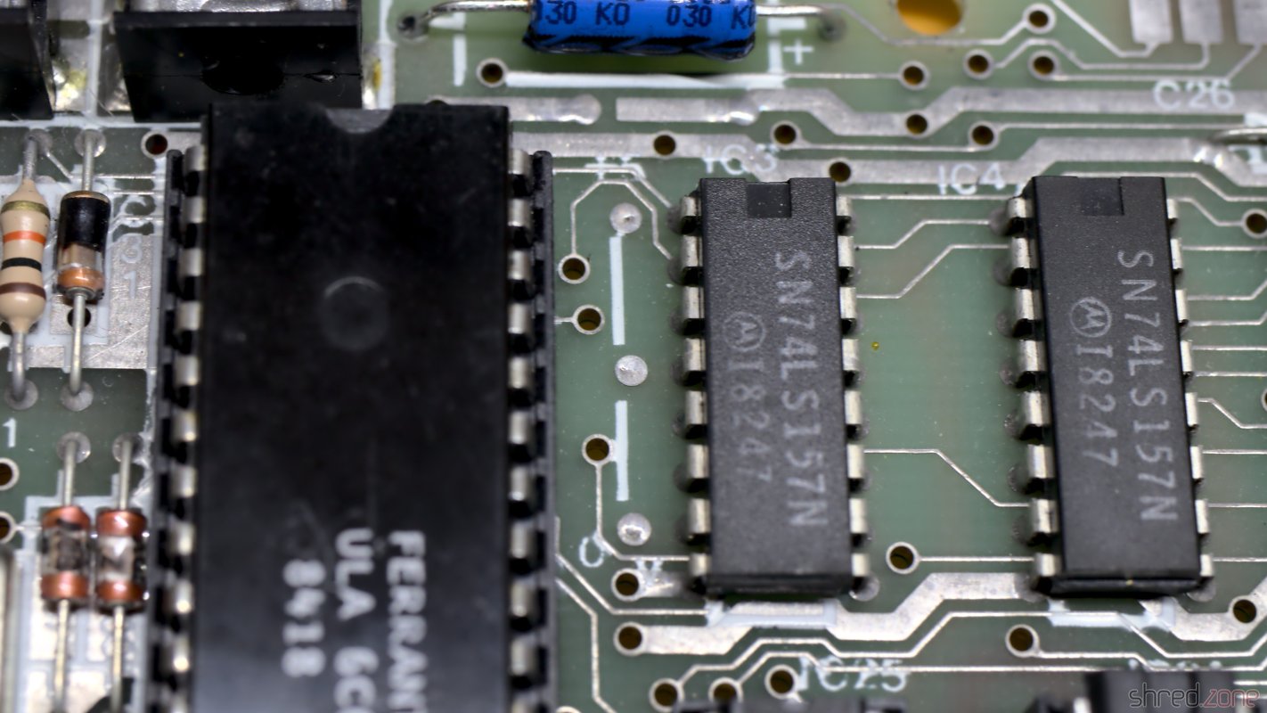
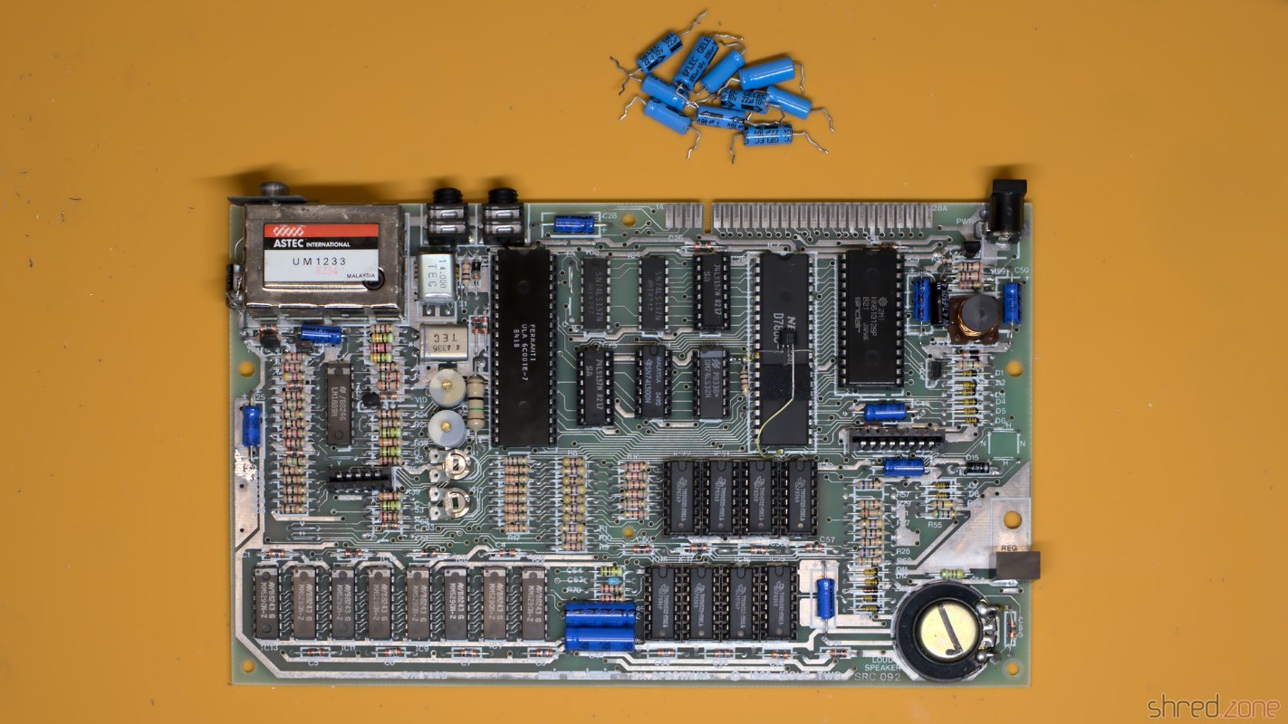
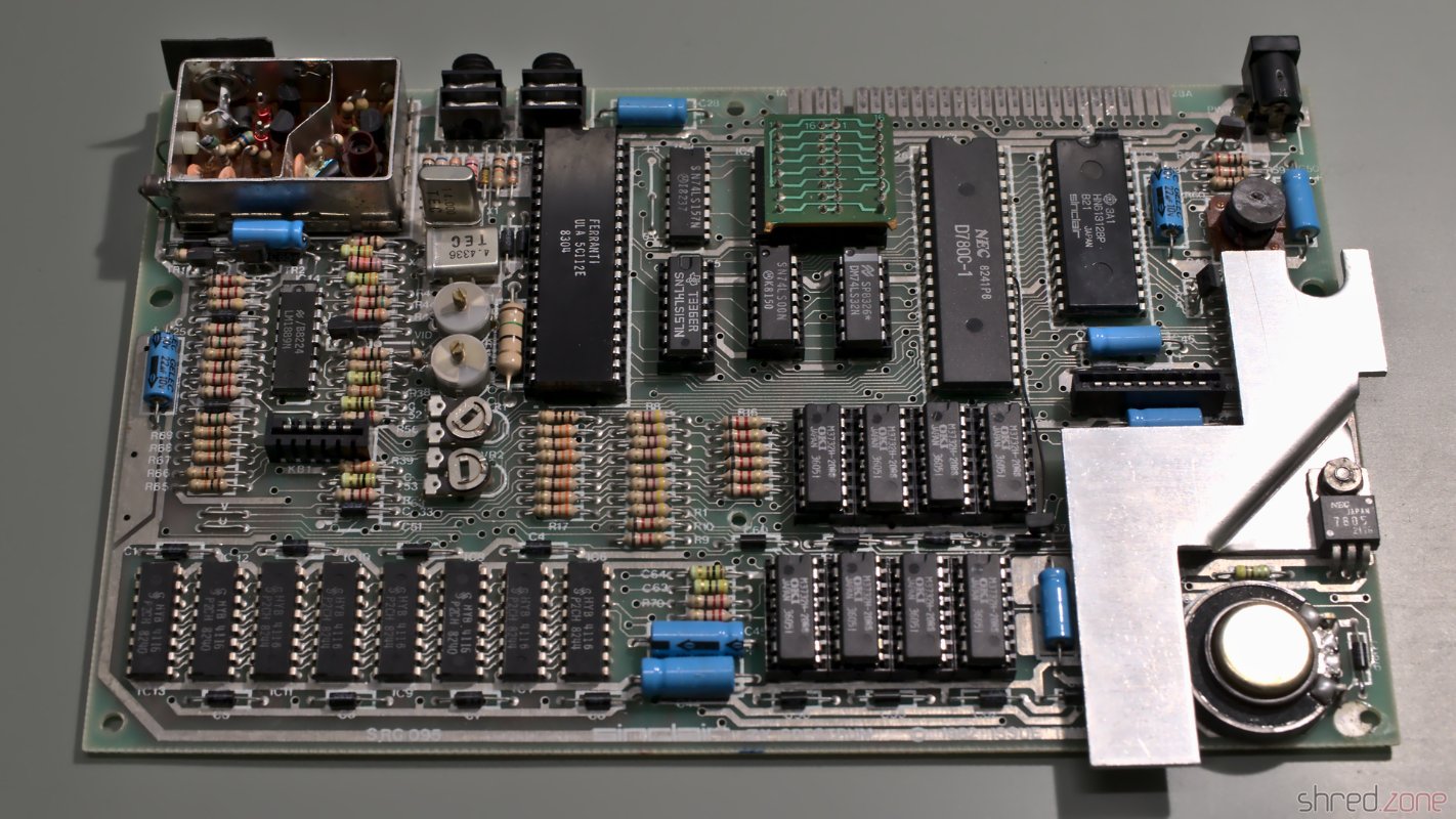
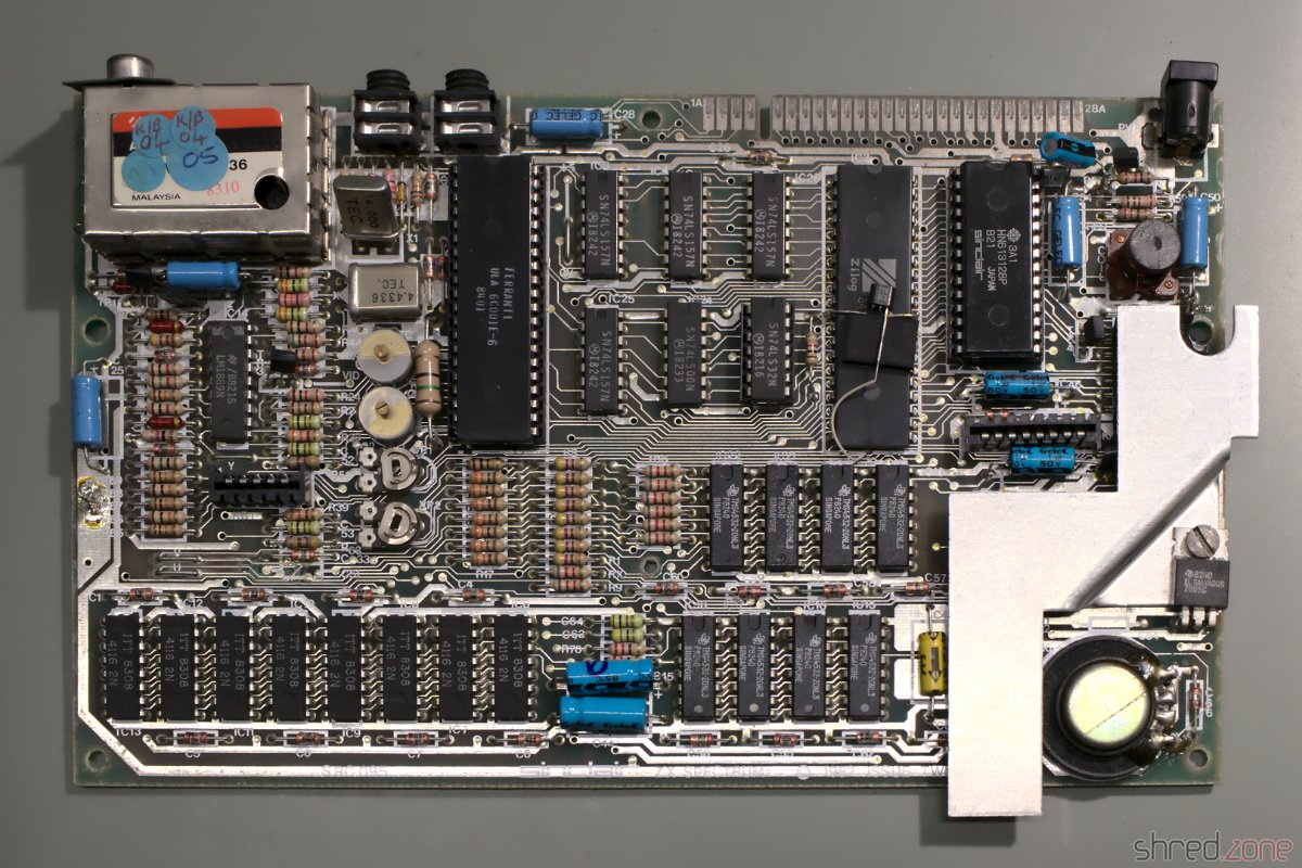
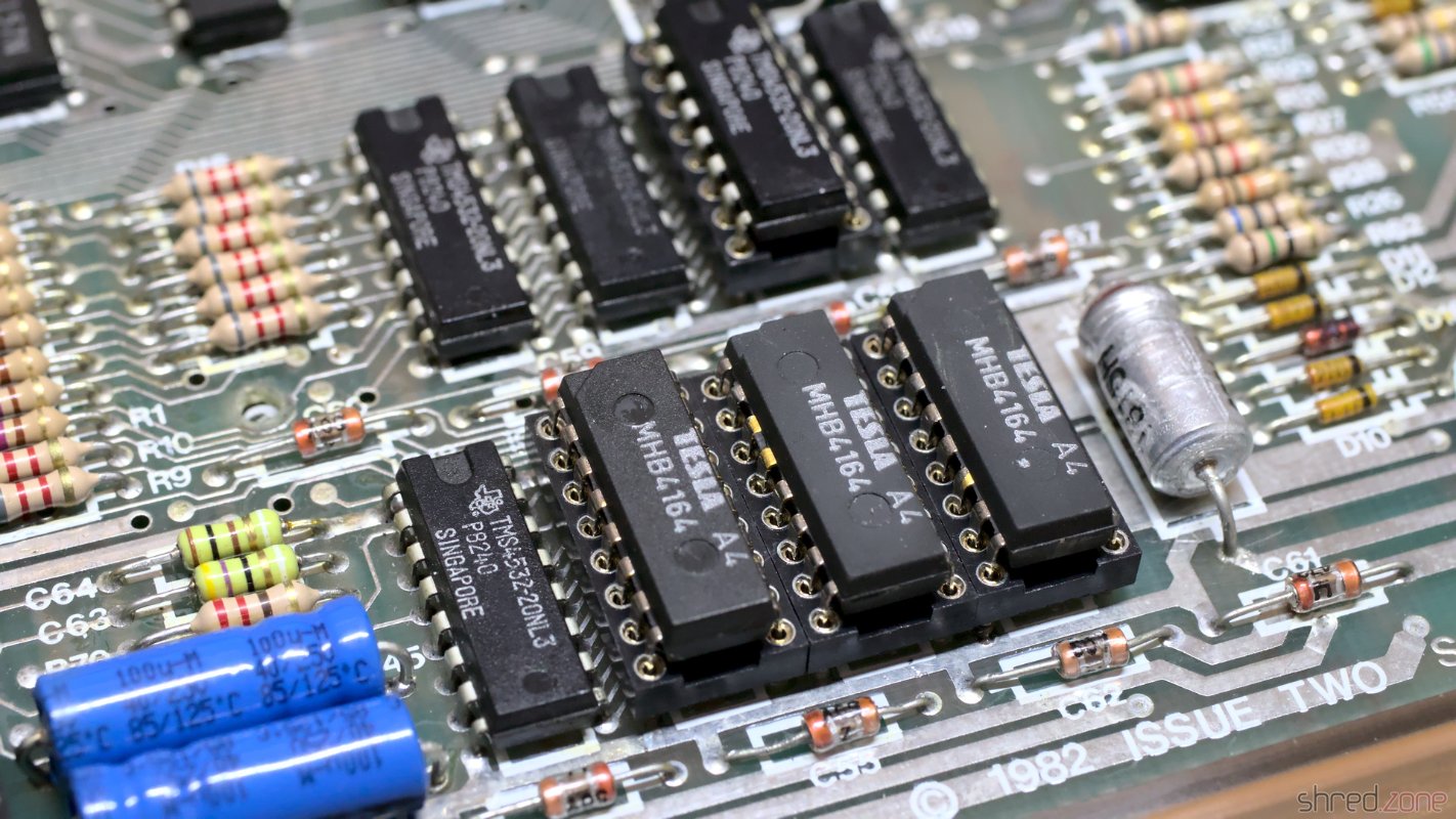
The Superfo Harlequin is a ZX Spectrum 128K clone. It is special because even though it's a 128K Spectrum, it still fits into an 48K Spectrum case. It's also special because the ULA custom chip is replicated by discrete 74HC-type standard chips that can be replaced easily if one of them should get broken. It's just a small advantage though, because the RAM chips, sound chip, and Z80 CPU are rare by now.

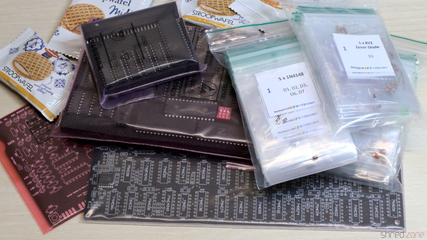
I have ordered the Harlequin 128K Black Large DIY Kit at ByteDelight. It comes with all components that are required to build the main board, even those that are difficult to find elsewhere. There is also a Flash ROM chip enclosed in the kit, but it does not contain a Sinclair ROM image for license reasons. What's still required to build a complete Speccy is a ZX Spectrum case with keyboard, and a Flash ROM programmer for the Sinclair ROM.

Assembling

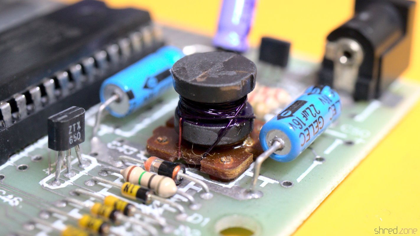
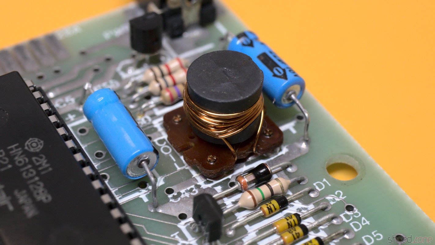
The Harlequin has only a single SMD component, and that one was even presoldered. All the other components are through-hole, so this DIY kit is even suitable for soldering novices.

The ByteDelight Harlequin kit. Also on the photo: The Diag Cart kit, en heerlijke Stroopwafels. 😋 How it started. The board, with the only SMD part already presoldered.

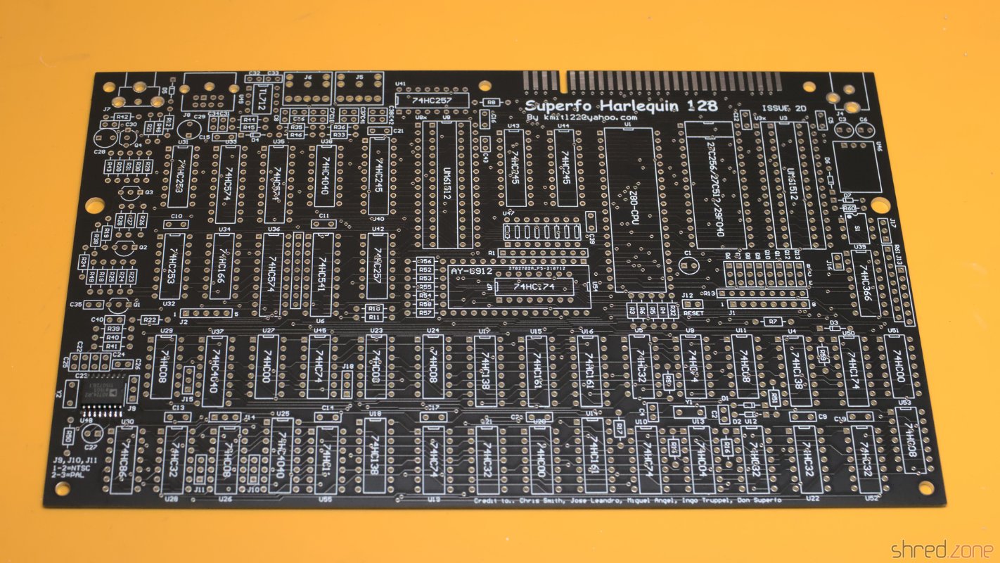
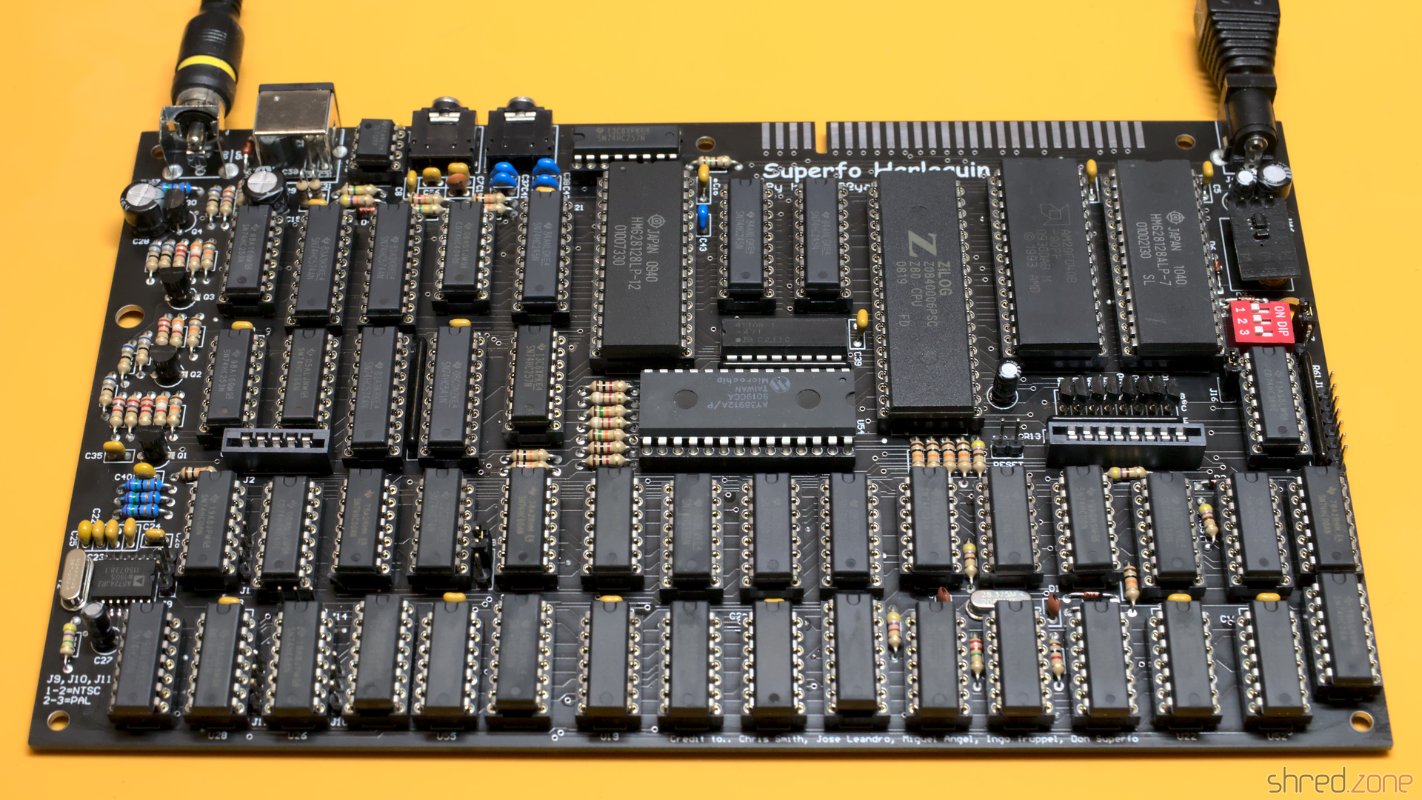
I spent the rest of the day with getting the components out of their bags, locating their correct location and then soldering them in. The ByteDelight kit was carefully assembled. Every component comes in separate bags per value, and are enumerated in their optimal order for assembling. It's literally just soldering by numbers. 😄

The most boring part was to solder in all the 51 sockets. The DIY kit came with standard sockets, but I generally prefer turned pin sockets, so I used that ones instead.

Completely assembled.

The kit also contains the crystal that is needed for an NTSC setup, so you can choose between a PAL and NTSC machine. The board itself is pre-configured for PAL though. For an NTSC machine, a few traces at the bottom side of the PCB need to be cut.

Flashing the ROM

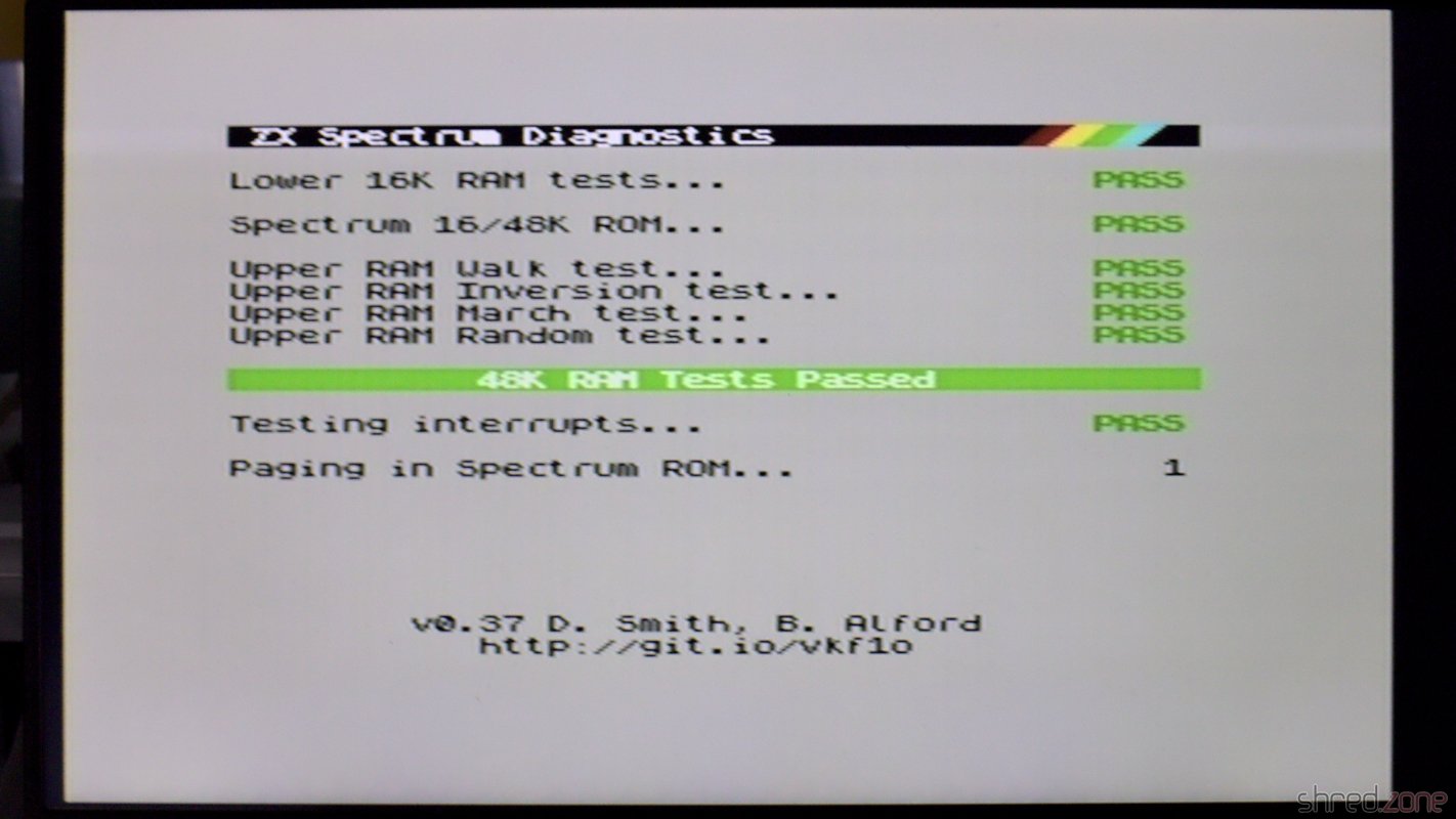
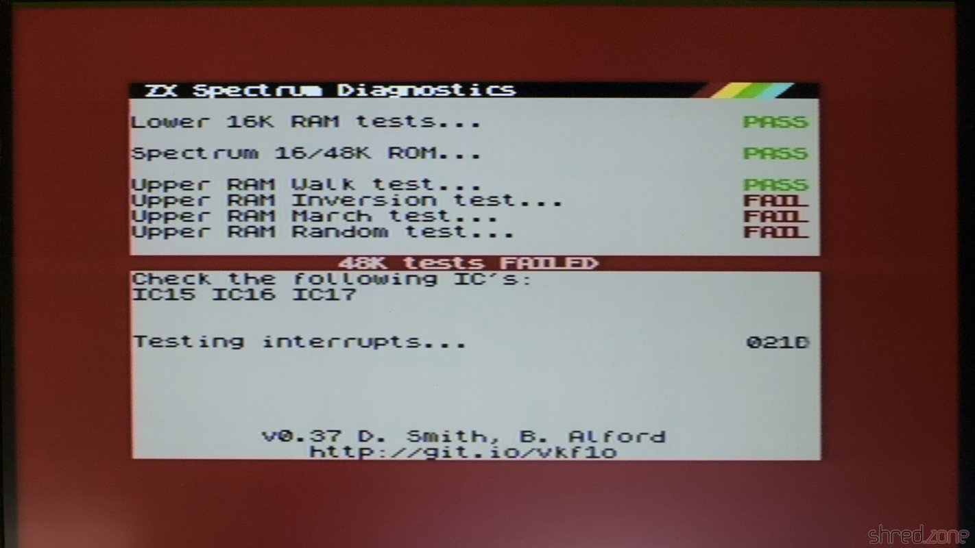
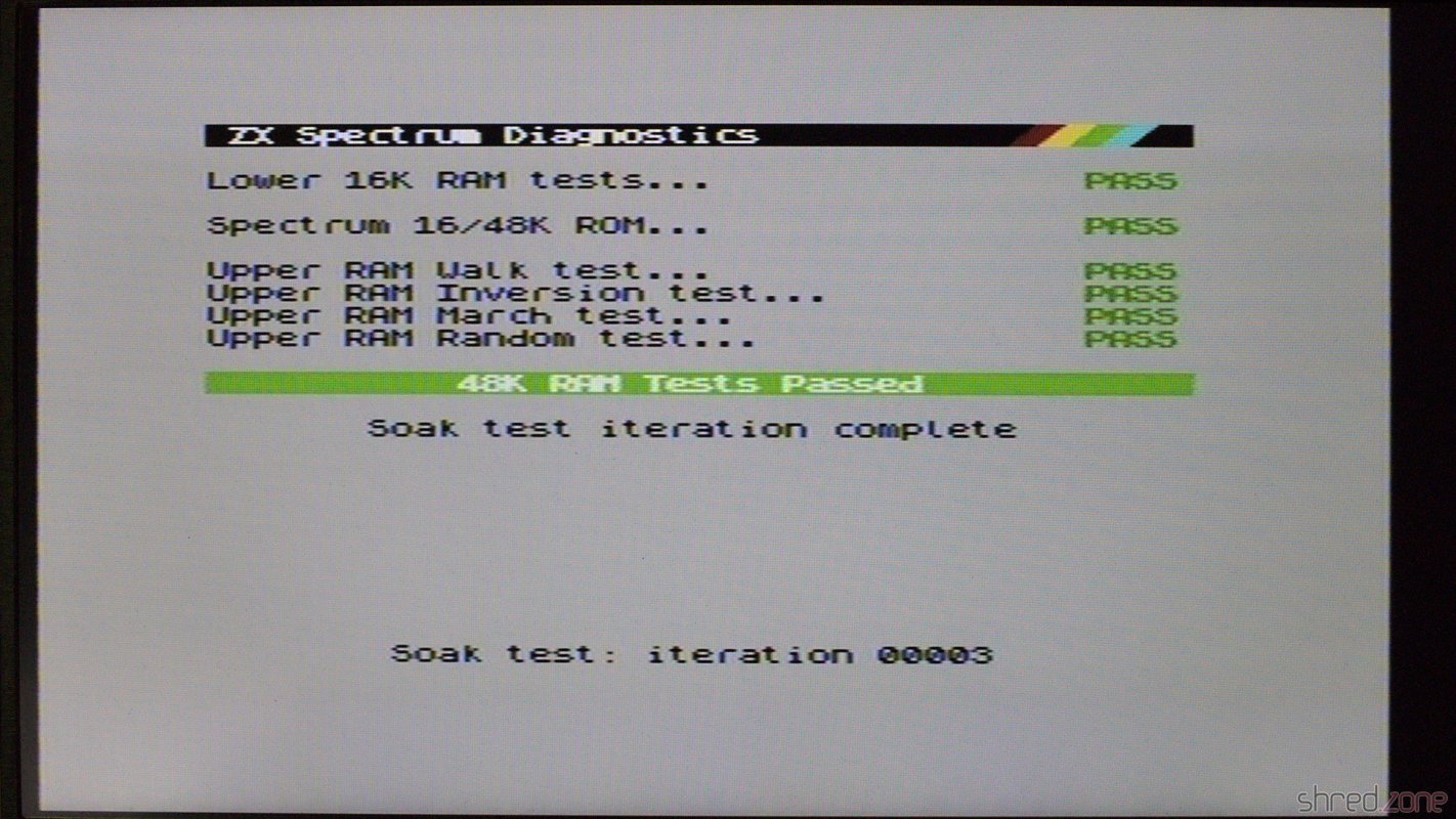
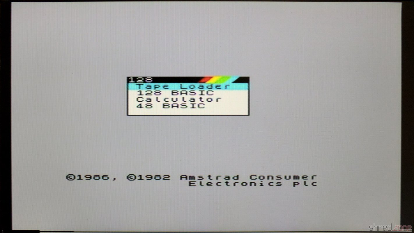
The DIY kit comes with an AMD AM29F040B Flash ROM. It is large enough to contain up to 8 ROM images. A DIP switch selects the image to be used. The pre-flashed image contains a Diag ROM, some other software, but no ZX Spectrum ROM for license reasons. The board itself also supports original Spectrum 48K and 128K ROMs, as well as 27C256 and 27C512 EPROMs.

ROM files can be found on the internet. I decided to keep the first six Flash ROM banks, and use bank 7 for a Spectrum 48K ROM, and bank 8 for a Spectrum 128K+2 ROM.

For flashing, I use the XGecu TL866II+ programmer and the minipro open source software. First I read the original content of the Flash ROM:

minipro --device 'am29f040b@DIP32' --read harlequin.bin

Then I made a copy of the first six banks. It's easy with the dd command. With a block size of 65536 bytes, the banks can be selected with the skip and count options. To keep the first six banks:

dd if=harlequin.bin of=harlequin-6banks.bin bs=65536 count=6

After that, I use cat to compile a new binary. Note that each bank must be 65536 bytes large, so if a ROM image is smaller, it must be duplicated (or quadruplicated):

cat harlequin-6banks.bin \
  48k.rom 48k.rom 48k.rom 48k.rom \
  128k+2.rom 128k+2.rom \
  > harlequin-new.bin

The new image can then be burned to the Flash ROM:

minipro --device 'am29f040b@DIP32' --write harlequin-new.bin

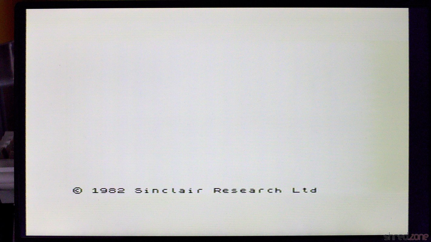
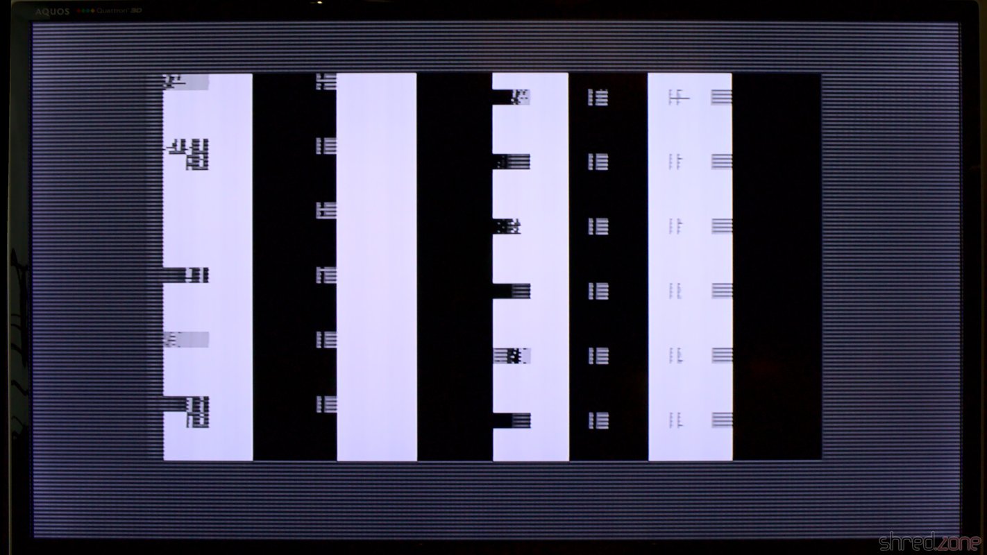
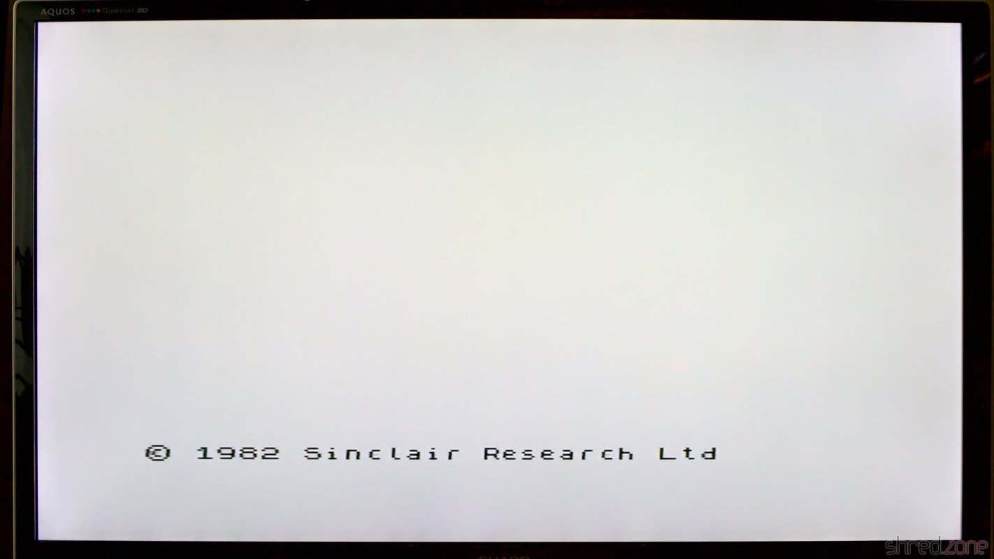
With the Flash ROM inserted into the Harlequin board, it was finally completed and ready for a first start. Unfortunately the maker of the Harlequin board saved a rectifier bridge, so it's still important to take care for the correct polarity of the power plug. Like the ZX Spectrum, the Harlequin needs a power supply with a 5.5/2.1 mm barrel plug with center negative. Most power supplys on the market are center positive.

The Harlequin is alive!

Even though the Harlequin has a lot more chips than an original ZX Spectrum, it is very frugal. It only consumes 1.7W at 9V, while the original Speccy consumes 4.8W. On the other hand, the Harlequin does not need 12V and -5V to run, so these voltages are not generated. This might be a problem for a few very exotic expansions.

The Case

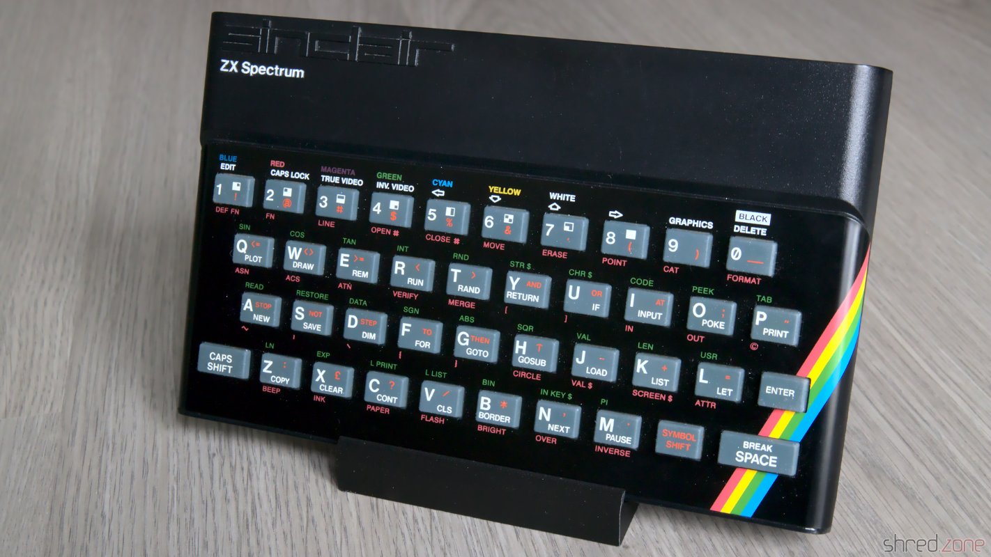
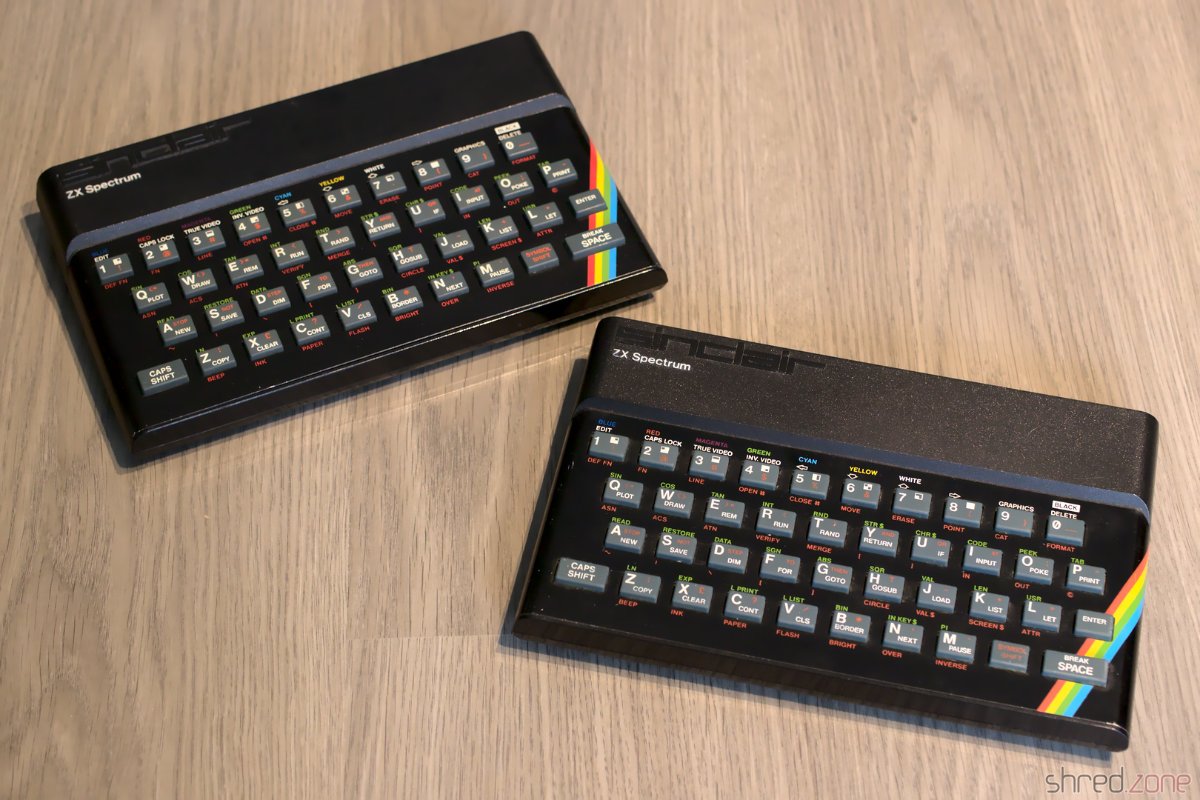
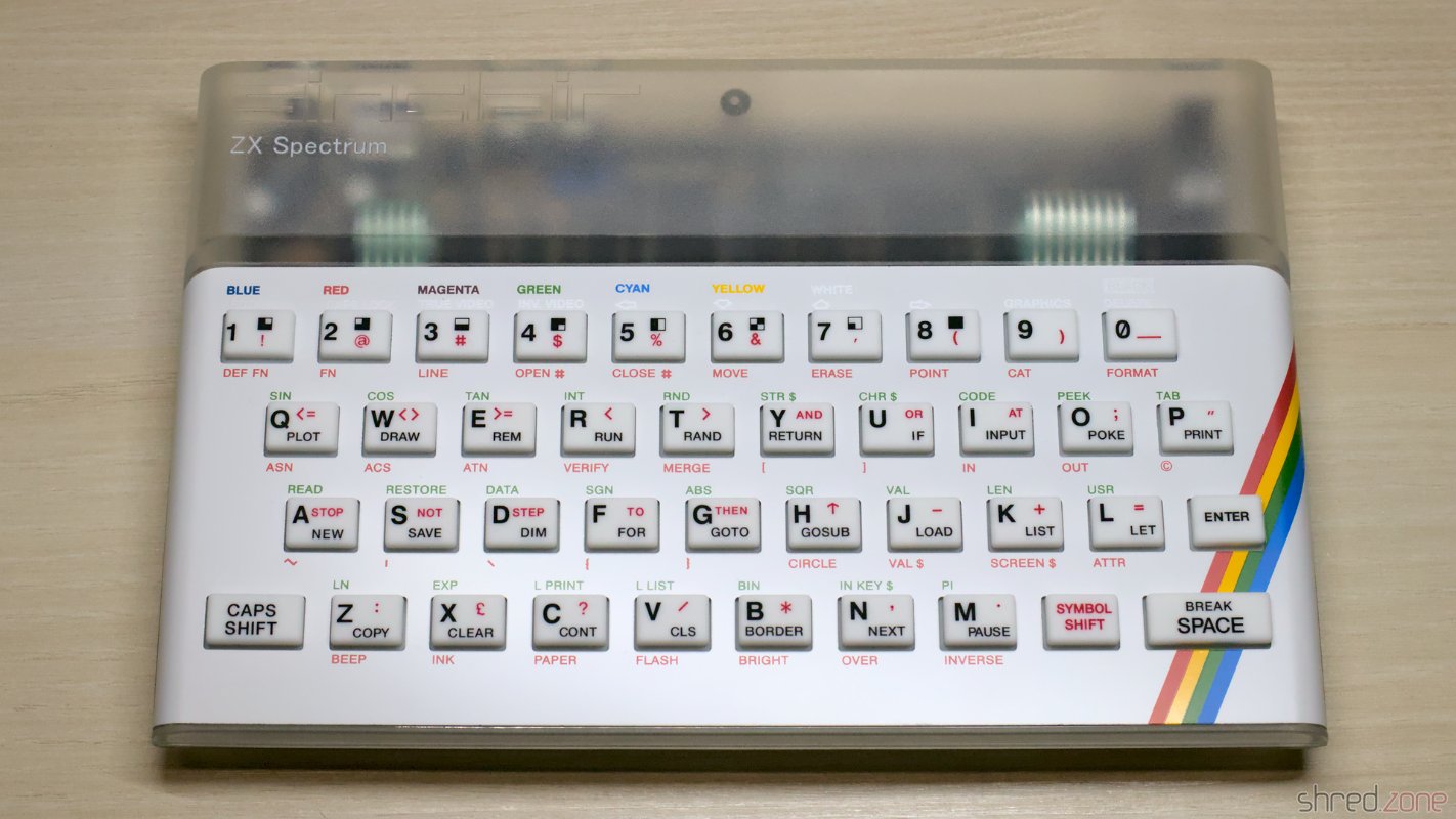
The DIY kit only comprises everything that is needed to assemble the main board. What's missing is a case with keyboard, and a power supply. The board has the same dimension as an original ZX Spectrum 48K board, so you can use original cases (e.g. the standard "rubber key" case or the ZX Spectrum Plus case), or buy a new replica case with new membranes, keymat and faceplate. The latter case is more expensive, but you get a brand new case in return, and you can pick from a large variety of colors.

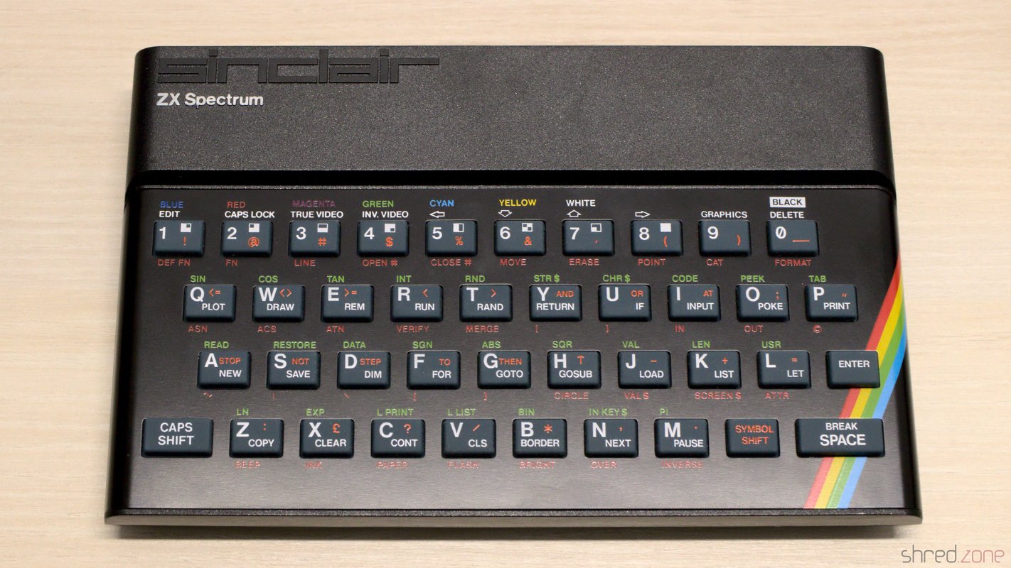
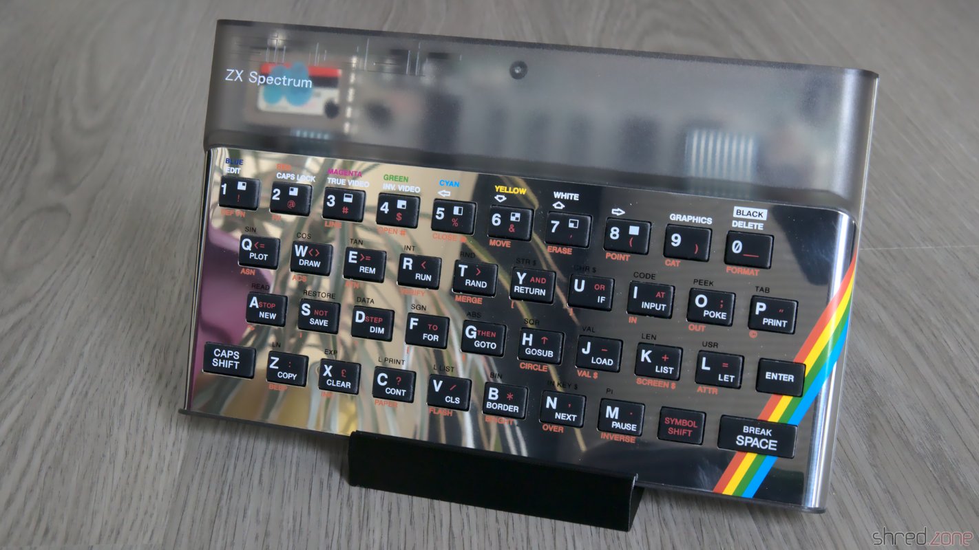
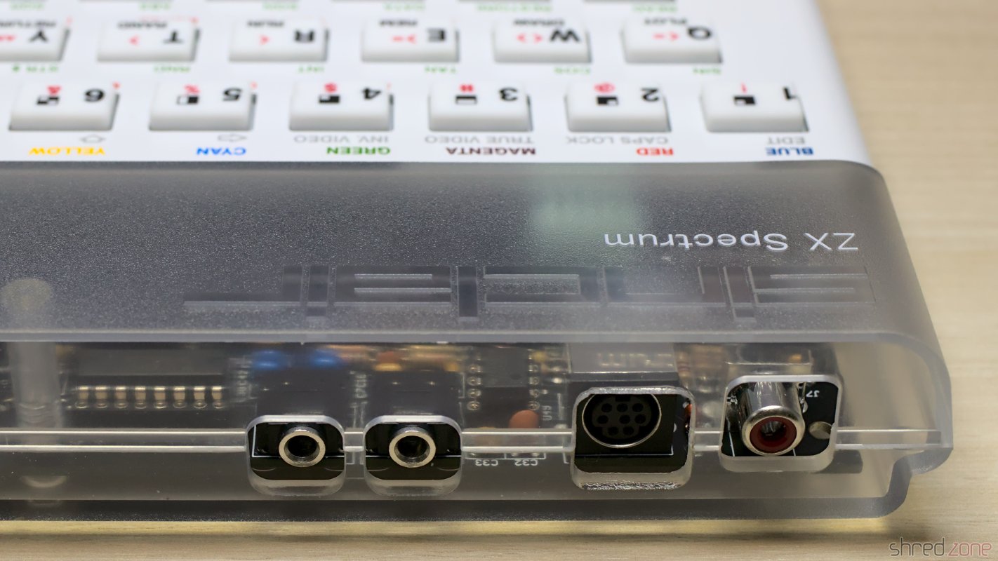
I decided for a white keyboard, and a transparent case so one can still admire the beautiful Harlequin board even inside a closed case.

A brand new ZX Spectrum 128K "Harlequin"!

The Harlequin has a separate RGB mini DIN connector. It is made in a manner so it won't interfere with a classic case. However you might want to use the RGB connector as it offers a much better image quality. Shops like ZX Renew offer special Harlequin cases with a cutout for the RGB connector. If you want to use a classic case, you might need to cut out a bit of the beautiful old case to access the connector.

From left to right: stereo audio, tape (mic/ear), RGB, composite

Since we are talking about making holes into old cases: The Harlequin has a built-in joystick interface. If you want to, you can cut out a space for a 9 pin Sub-D male connector, and wire it to the board. I refrained from making a cut into my beautiful Harlequin case, and use a classic Kempston joystick interface instead.

Let's Play

The simplest way to load software into the Harlequin is by the Mic/Ear port. There are smartphone apps and also a lot of tools that can generate the sounds to load TAP or TZX files, so there is no need to dig out the old tape recorder and audio cassettes.

I am using my tzxtools. The tzxplay command plays back TZX and TAP files to the standard audio output. I connect the sound card output to the mic/ear connector using a classic phone jack cable.

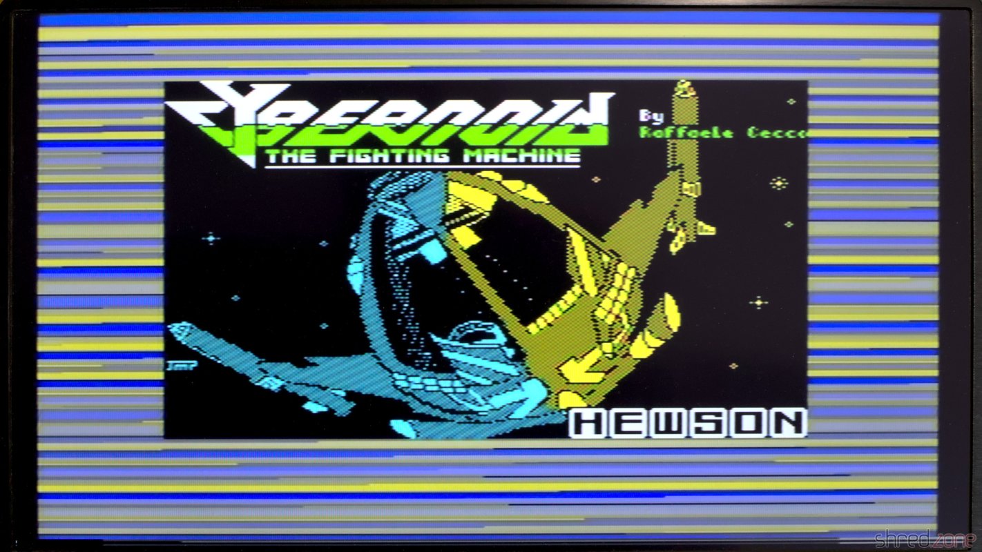
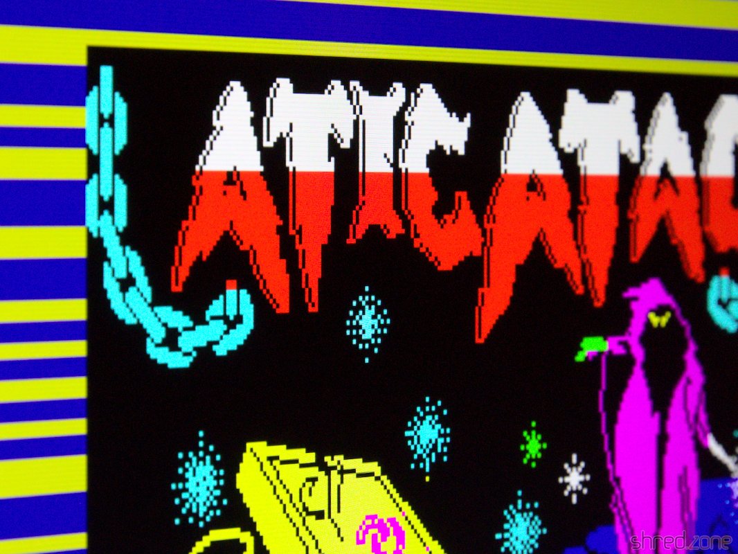
Since the Harlequin is a full-featured 128K clone, it also comes with an AY-3-8912 sound chip and even a stereo output. So the first thing I did was loading a game that makes use of that soundchip for in-game music.

The 128K version of Cybernoid uses the AY-3-8912 sound chip.

ZX Spectrum "Beauty"

When I started to refurbish old computers in 2021, I couldn't imagine that it was so much fun. 😁 The other day I bought another ZX Spectrum. According to the seller, it had some strange artefacts on the screen and also stability issues, so it was sold as defective. When I tried it at home, it was even worse. I just got a black screen on a white border.

Screenshot made by the seller. Here the screen was just black with a white border.

Inside the case I found an Issue 2 board. The previous owner has added a composite output on a separate connector. As the age of TVs with tuners is definitely over, there is no need to keep the modulator output. I will do my own composite mod instead, and remove this ugly cable that was hanging out.

The manufacturing dates of the components tell an interesting story. This computer has probably been manufactured around the end of 1982. However, all chips that are related to the upper 32KB RAM are socketed, and some were made in 1983. I guess it was originally built as 16K model, and has been extended to the full 48K a year later. As the only chip on this computer, the ULA was made in 1984, so maybe it had been replaced around then.

It's an Issue 2 board with a composite mod on a separate connector. I removed the ULA for testing.

My main suspicion was that the ULA was broken, so I put it into one of my working Spectrums, and was happy to find it in working order. The problem must be somewhere else.

The usual first step is to check the voltages. And bingo, the 12V line had around 7V, and the -5V line was flat. This sounded very familiar, and a look at the coil confirmed my suspicion. The coil had a purple color, and a short between the primary and secondary winding. I guess the coil was already pre-damaged when the Spectrum was sold, causing the artifacts because of poor voltages on the lower RAM chips. When I powered up the computer at home, I eventually killed it.

Well, it's not the first time I had to deal with a broken coil. I unsoldered it, rewound it, and replaced the semiconductors that usually get grilled as a result. Then I powered the system again, and found that all voltages were back to normal. Success!

A shorted coil. The purple color is looking very familiar. It was the same on another Spectrum. The repaired coil.

I put the ULA back into its socket, so I could check what else is broken. And (to my displeasure, to be honest) the computer just came up and was working again.

This is looking good! The computer is working again!

What a spoilsport! I was hoping to have some more repair fun with that machine. 😉

Okay, what next? I started with replacing the electrolytic capacitors with fresh ones. Then I found something strange: A wire link was missing that was supposed to be there.

There is supposed to be a wire link here.

That link is important. The upper 32K RAM chips are actually 64K RAM chips, where one half of the memory turned out to be faulty after production, so they were sold with half the size for cheaper. The link configures which half of the memory is to be used. There is no pull-up resistor, so keeping it open is not a valid option. It might cause the upper RAM to randomly flip between the working and faulty memory half. I doubt that this computer has ever been working stable after it was modified to 48K. This link has just been forgotten by whoever did the modification.

The RAM chips are TMS4532-20NL4. The trailing 4 indicates that the upper part of the memory is to be used, so I added a link between the center hole and the "+5V" hole. A trailing 3 would require a link between the center hole and "0V".

I soldered in the link and replaced all electrolytic caps with Vishay ones. I also replaced the 7805 voltage regulator with a Traco Power TSR 1-2450. This modern DC/DC converter is a drop-in replacement that needs no heatsink, and is small enough to still fit into a classic ZX Spectrum case.

Wire link added and electrolytic capacitors replaced.

Issue 2 Spectrum boards have two variable resistors, VR1 and VR2, for color calibration. With the aid of an oscilloscope, calibration is a matter of a minute. I connected the scope to the composite video output (or to the video input of the modulator), and then adjusted both resistors until the signal was looking as smooth as possible. There is a blog article at Spectrum for Everyone that gives more details about the calibration.

Finally, I ran the ZX Spectrum Diagnostics tool. All tests passed, even those of the upper RAM.

All diagnostic checks passed.

Another repair job well done. 😄

So there is my 3rd ZX Spectrum. Above all, I like the exceptionally good condition of the case. It seems that the computer has barely been used in its 40 years. The keys and faceplate actually look pristine, and there are also only very few and small scratchmarks.

The case is in an excellent state, considering it's 40 years old.

ZX Spectrum "Recoiled"

From my first days of home computing, I still have two ZX Spectrum 48K. The first one is my own one, which I restored in the previous part. This second Speccy was a donation from a friend. It was broken and written off as irreparable, so he wanted to throw it away, but I asked him to give it to me instead.

Let's find out what we have here…

Memorable Surprise

This Speccy also has an Issue Two board, but it seems to be a bit older because it has an older ULA 5C112E-3, while my own one has an ULA 6C001E-6.

Another Issue 2 board.

What surprised me was the tiny daughterboard that is used for IC26.

This one is having a tiny daughterboard though.

I first thought it was some kind of post-production fix for a PCB error, but it turned out to have a much simpler explanation. For the upper 32K RAM, Sinclair used eight 32KBit DRAM chips of various manufacturers. Those chips were actually 64KBit chips, but one half of the memory turned out to be defective after production, so they were sold with half of the capacity for cheaper.

To run a Spectrum, all eight of the chips need to have the defect in the same half. A wire bridge on the board then configured whether the "upper" or "lower" half of the RAM was to be used. For the OKI M3732 chips that were used on this board, the internal memory cell addressing is a bit different though. Let's put it that way, on these chips either the "left" or "right" half was defective. The tiny daughterboard just takes care of the necessary modification on the address lines to run the OKI chips. Maybe they have just been the cheapest around when Sinclair produced this batch. Starting with the issue 3 boards there were jumpers for the OKI chips, and the daughterboard was not needed any more.

Damage Assessment

In order to see anything, I first did the "composite mod" that I also did on my other ZX Spectrum. It just needs a wire and a few minutes of work, so it is well invested time even if this ZX Spectrum actually turns out to be irreparable.

After that, I connected the Speccy to the TV, took a deep breath, and then turned on the power.

This isn't looking good.

Yes, this computer is definitely broken.

New Coil

The first thing that should be tested on a broken ZX Spectrum is if the voltages are correct. The 4116 RAM chips need three of them: +5V, +12V, and -5V. The +5V were there, but instead of +12V I only got +7V, while the -5V were completely missing.

With further checks I found the culprit: the coil was shortened. And there must have been a lot of heat involved, as the insulation plastics was completely melted and got a dark purple color. The left photo shows this coil, the right one shows a good coil for comparison.

The insulator is melted. The primary and secondary side are shorted.This is how a good coil is supposed to look.

That kind of damage usually happens when an expansion cartridge is removed while the ZX Spectrum is still powered, causing a short circuit on the power lines. This poor computer must have given one last smoke signal before its decease.

The coil was custom made for the Spectrum. One can still get remakes today, but they are quite expensive. So why not just wind a new one myself?

First I thoroughly removed all the old copper wire and the charred insulator plastics. I was hoping that I could just unwind the old coils and count the number of windings, but the insulation was melted to a single lump of plastic. The wire eventually tore, and I had to use a cutter to get the remains off the ferrite core. When I was done, it looked like the coil just exploded on my desk.

The battlefield.

Luckily, the circuit diagram gives us all the information we need to know.

The original coil wire had a diameter of 28AWG (or 0.32mm), so we need insulated transformer copper wire of the same strength. For the inner coil we need about 30cm of wire, for the outer coil about 100cm.

First we start with the inner coil. Wind a bit of the wire firmly around the pin marked in red on the next photo, then do 13 turns around the ferrite core, then wind the wire firmly to the other pin. The windings on the ferrite won't need to be perfect, but should still be as tight as possible. I recommend to rewind the inner coil even if it appears to be intact, as the insulation might already be damaged.

After that, we do the same with the outer coil, having 39 turns. It is important that both coils are wound in the same direction. It doesn't matter whether both coils are wound clockwise or counter-clockwise, as long as you use the same direction for both coils. The original coils are wound counter-clockwise when looked from above.

First the inner coil with 13 turns, then the outer coil with 39 turns. Start with the pin marked red. Use the same direction for both coils.

Finally, use a lighter to remove the insulation on all four pins, then use flux and a bit of solder to fix the wire ends to the pins. Now check with a multimeter. Both the primary and secondary coil should have less than 1Ω, but there should be no resistance between both coils.

The wires are wound around the core, and then wrapped around the pins. The refurbished coil, ready to be soldered back.

Now the coil can be soldered to the board again. The fifth pin serves as a key for the correct orientation.

I could only get 0.35mm wire, so my coil got a bit too "fat".

A shortened coil always causes secondary damage, so I preemptively replaced the components that usually fail as well:

  • TR4: It can (and should) be replaced with a ZTX651, which is stronger and more reliable. They can still be found at good electronic retailers. I was researching for a standard transistor as replacement, but even though there were some types, the ZTX651 was always the strongest recommendation.
  • TR5: The original type is not available any more, but can be replaced with a ZTX751 or a standard BC557 (which must be mounted facing in the opposite direction).
  • D16: This can be any standard 5V1 Zener diode.

After that, I connected it to power, and (to my surprise, to be honest) all the three voltages were back and correct.

What's Next?

The picture on the TV was still unchanged, but I had already expected that more components would be damaged.

I checked the temperatures of the ICs with my finger. If you try this at home, be very careful because a broken chip can get so hot it can easily burn your skin within a second.

The ULA got warm, but that's normal. The CPU also got a bit warm, which wouldn't be a surprise on modern computers, but the Z80A is supposed to stay cold. I unsoldered it, and replaced it with a 40 pin socket and a used SGS Z80A CPU that I once recovered from a broken ZX-81.

I powered it up again, and it just worked! 🎉

So there was just a burnt coil and a broken CPU. This repair was much easier than I had expected.

Finishing Works

Like on my other ZX Spectrum, I first replaced all the old electrolytic capacitors. I also used a fresh 7805 voltage regulator, and thermal paste for better cooling.

My first Spectrum got a transparent case and a chrome faceplate. For this ZX Spectrum I decided to keep the original look, so I just replaced the broken keyboard membrane. The old faceplace had some visible dents and scratches, so it was replaced as well. I then washed the original case in warm water with a bit of dish detergent, and then put it all back together.

The restored ZX Spectrum 48K.

And that is the story of the two sisters who got a nice makeover, and are now fit for the next 30 years. 🙂

ZX Spectrum "Chrome"

I still own two ZX Spectrum 48K from my very early days of home computing. The first is my own one, I got it from my parents as a Christmas present back in 1985. The other one was owned by a friend. It was broken and couldn't be repaired, so he first intended to throw it away, but then gave it to me instead.

So here are the two sisters…

Two Sinclair ZX Spectrum 48K

This article is about the restauration of my own ZX Spectrum. There will be a follow-up for the other one.

Let's have a look under the hood. This Speccy has a standard Issue Two board, with a floating transistor on the CPU as an usual factory modification of that board.

My own Speccy. The ROM, ULA, and a 74LS532 are socketed.

It looks alright so far. Let's find out if it is still working.

Composite Mod

All home computers of that era were designed to be connected to the "antenna in" of an ordinary color TV. The TV was tuned to UHF channel 36 to receive the signal. The picture quality was quite okay back in those days, but poor for today's standards.

Today, almost all TVs have a composite input, so there is no need for modulating the signal any more. Luckily the ZX Spectrum can be easily modified to give a composite signal. First, the two existing wires on the side of the TV modulator are unsoldered and just bent to the side (so the mod can be reversed if desired). Inside the modulator, the resistor is disconnected from the RCA jack. Then a new wire is connected from the outside's former signal pad straight to the RCA jack.

The old two wires are removed. A new wire is connected to the left "signal" pad.Inside the modulator, the resistor is disconnected, and the wire is soldered to the RCA jack.

After that modification, the Spectrum can be directly connected to the TV's "composite in". The modification can be easily reverted, and there is no need to drill an additional hole into the case.

Testing

I have lost the original ZX Spectrum PSUs, but any stabilized 9 V PSU with at least 1.5 A will do as a replacement. It is very important to check the polarity of the barrel plug! Most modern PSUs have the positive pole at the inside of the plug, while the ZX Spectrum expects the positive pole at the outside:

Many Speccys certainly have been killed by using a replacement PSU with the wrong polarity.

I powered it up, and to my surprise it was still working!

Almost 40 years old, and still working.

All I would need to do now is giving it the usual technical overhaul.

Recapping

The first thing is to replace the electrolytic capacitors. The old ones dry out over the years, and lose their capacity. Some may even leak and damage the PCB.

To keep the old look, many people prefer axial caps with the classic shape and a blue (or at least black) color.

High quality axial caps are difficult to find and quite expensive. I chose to use Vishay capacitors with an expected lifetime of 2,000 h. However the reference photos of the retailer deceived me. The nice black "classic" caps turned out to have an odd shape, and an aluminum or plastic grey color. They are not of an inferior quality, quite the contrary, but they just don't look vintage. I still decided to use them.

Shiny new caps that should last for much longer.Sadly these ones don't have a classic look, but they will do their job.

There is a trap on the Issue 2 boards: the polarity of C46 is indicated backwards on the silkscreen. The capacitor must be installed with the positive end to the left.

C46 (the upper one) is correctly installed with the positive end to the left, while the silkscreen claims it's on the right.

After the recapping, I thoroughly washed the board with IPA and a toothbrush. Then it was time for another test.

Operation Successful…

…but the patient died. This is what I saw when I powered it up again:

This doesn't look good...

Obviously I broke something. 😯 But what?

I first checked the voltages, but they were all right. No chip was getting hot, except of the ULA, but that's normal.

The ROM chip is socketed, so I removed it. Without the ROM, the CPU always executes the same instruction (RST 38h), which fills the memory and results in a distinct screen pattern.

Screen pattern without ROM, indicating that the CPU is working.

The pattern was there, so the CPU was fine, but it had some noise in it. I suspected a broken RAM chip, and the signal on the data bus actually looked a bit strange on the scope. I started to replace a few suspicious RAM chips, but to make a long story short, it didn't change anything. I was clearly on the wrong track.

I tested the ROM, but it was fine. I swapped the ULA with the one from the other Speccy, but it didn't help either. I checked all the capacitors I had replaced, but they had the correct values and orientation, even that infamous C46.

What has just happened that damaged a previously working Spectrum so badly?

I noticed that, as the only standard chip, IC23 was socketed on that machine. It must have been from a previous repair, because unlike all the other soldering joints, the lead was yellowish there. When I touched the joints with the tip of my soldering iron, they were also sizzling. This was just scrap. I completely removed the old lead, and soldered in a new socket.

Could this have been the problem? I gave power to the Speccy. And yes, it was working again! 😄

I guess that when I cleaned the board with IPA, I partially dissolved the flux in these old soldering joints, making them cold. IC23 is used for the proper access timing of the upper RAM. With a bad timing, the upper RAM might just have disturbed the entire data bus.

Finishing Works

With the Speccy brought back to live, I did some final cleanups.

A defective TR4 is a common cause for a broken power converter. It was still working here, but I precautionary replaced it with a ZTX651, which is the more reliable successor type.

I also preemptively replaced the 7805 voltage regulator by a fresh one, and used thermal paste for better cooling. It's common in the retro scene to replace the 7805 with a modern step-down converter that does not need any cooling, but I decided against it. I like to feel the heat of a working ZX Spectrum.

The ribbons of the keyboard membrane got brittle over the years, and already started to break. Luckily there are new membranes available on the market. And since I was on it, I also ordered a transparent replica case, a black rubber keyboard mat, and a chrome faceplate. I especially like the idea of a transparent case making the inside of this old computer visible.

The restaured ZX Spectrum 48K "Chrome Edition"

The first of both sisters is restored now. The other one might be more difficult to restore though, as it was said to be "broken beyond repair". Let's find out.

Addendum

Never claim a repair is done before you ran some diagnostics. Some months later, I tested this Speccy with a Diag ROM and found that three upper RAM chips are defective.

Three upper RAM chips have failed the tests.

Fortunately the Diag ROM gives exact advice about what RAM chips need replacement. It was also fortunate that I had a sufficient number of spare chips on stock.

The faulty RAMs were replaced by new MHB4164 ones. And no, it's not that Tesla company.

The advantage of the MHB6164 chips I used is that they are true 64KBit RAMs, so I don't need to take care that they match the other TMS4532 RAM types. After replacement, all diagnostic checks were finally green.

The upper RAM is working, and all tests are green now.

R Tape loading error, Part 2

In the first part I showed how the Sinclair ZX Spectrum stored data on tape. This second part explains what is stored, and what causes a tape loading error.

The ZX Spectrum BASIC offers a SAVE command for saving all kind of data. It can be used to save a BASIC program, variable arrays, but also arbitrary parts of memory. These files are always saved in two separate blocks. The first block is called header. It contains the file name, data type, and other meta information. The second block follows about a second later and contains the data itself.

The internal structure of each block is identical. The first byte distinguishes between header ($00) and data blocks ($FF). The final byte is a parity checksum. Everything between these two bytes is the payload.

A header block always contains a payload of 17 bytes. The first byte identifies the file type, followed by the file name (10 characters), followed by the length of the data block, and closed by two optional parameters that have different meanings depending on the file type. The length and the two parameters consume two bytes each, with the lower byte coming first because the Z80 CPU is little endian.

This is an example header block of a screenshot:

00$00 = Header
0003$03 = Binary file (Code or SCREEN$)
0153S
0268h
0372r
0465e
0564d
062E.
077Az
086Fo
096En
1065e
11001BLength: 6912 bytes ($1B00)
130040Parameter 1, here: starting address ($4000)
150000Parameter 2, here: unused
20Parity

A screenshot is actually just a memory dump that starts at address $4000 (which is the starting address of the screen buffer) and is exactly 6912 bytes long (the ZX Spectrum has a resolution of 256×192 monochrome pixels plus 32×24 bytes color attributes, giving a screen buffer size of 6912 bytes).

For other file types, the two optional parameters have different meanings. For example, a BASIC program file stores the line number to start at after loading.

The final byte is the parity. It is used for error detection, and computed just by XOR-ing all the bytes that have been read. The result must be $00, otherwise a "R Tape loading error" is reported.

This kind of error detection is rather weak. Due to the nature of the XOR operation, two wrongs give a right. This means that when the block contains an even number of bad bits at the same position, they will be undetected. It is also not possible to correct reading errors, as the XOR operation only allows to identify the position of the bad bit, but not the actual byte that contained the error. More sophisticated error correction algorithms would have slowed down the loading process, though.

The parity is computed as a final step, after all the bytes have been read from the block on tape. For that reason, the loader can only decide at the end of the recording whether the loading was successful or not.

But then, why does the tape loading error sometimes appear while the block is still loading? Well, in the first part I have explained that the loading routine just reads an unknown number of bytes. It ends when waiting for a pulse change took to long. Now, if there is an audio gap on tape, the signal seems to end just in the middle of the block. It is then very likely that the parity checksum is wrong because there are still bytes missing.

Some simple copy protections made use of the way the Spectrum loads data from tape. A very common way were “headerless” files, where the header block was left out and only the data block was recorded on tape. The BASIC LOAD command was unable to read those files because of the missing header.