Peace Memorial Park, Hiroshima

Atari ST

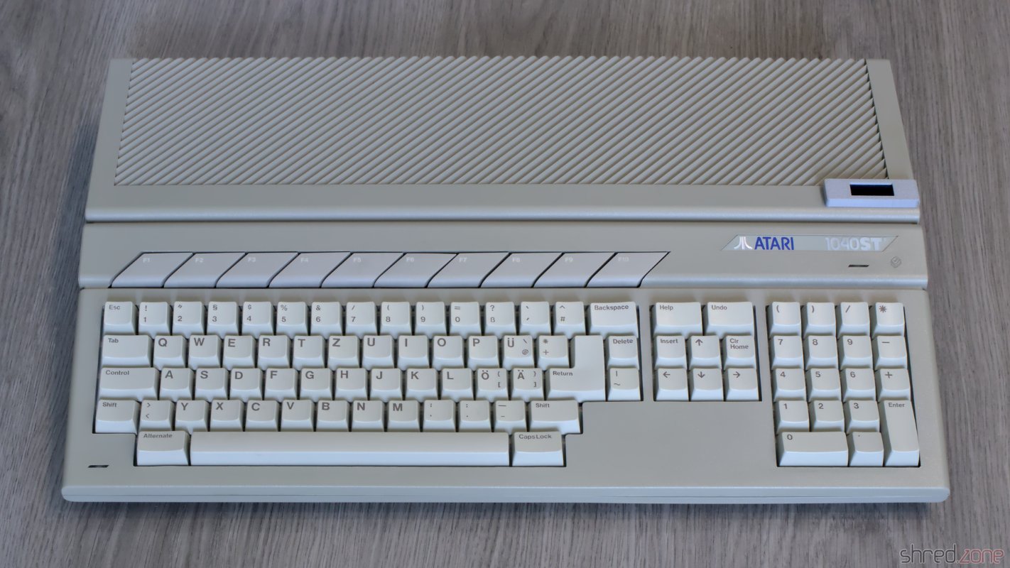
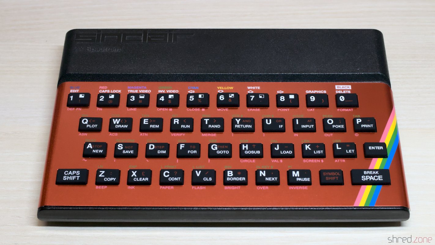
At the end of the 1980s, I wavered between the Atari ST and the Amiga 500 to become the successor of my ZX Spectrum. Eventually I decided to get an Amiga. In retrospective it was the right choice. The AmigaOS laid the foundation to my later career as a professional software developer. Still I stayed curious about the Atari ST. Well, now is the time to get one. πŸ˜€

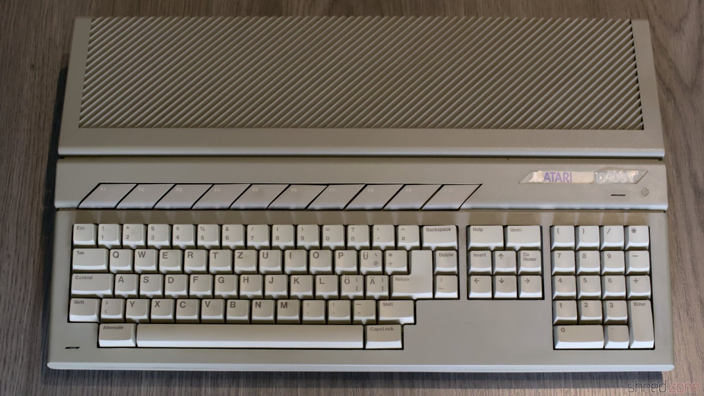
I found an Atari 1040STF for a fair price. The outside is in a very good condition. No modifications, no yellowing, even the warranty seal was still intact. Also on the inside, there was just a bit of dust around the case vents.

My new Atari ST. Outside it's in a good condition. Even the protective film is still on the Atari badge. Just a bit of dust inside.

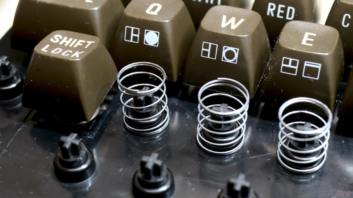
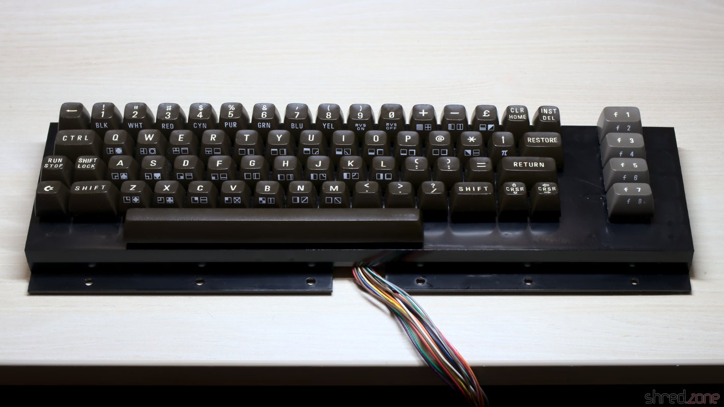
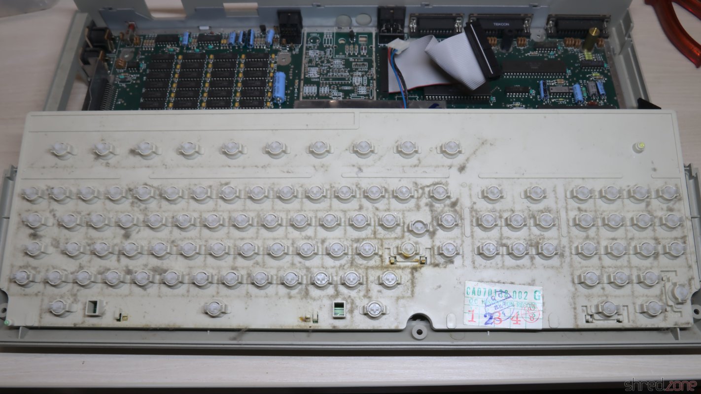
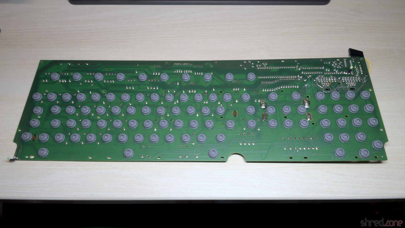
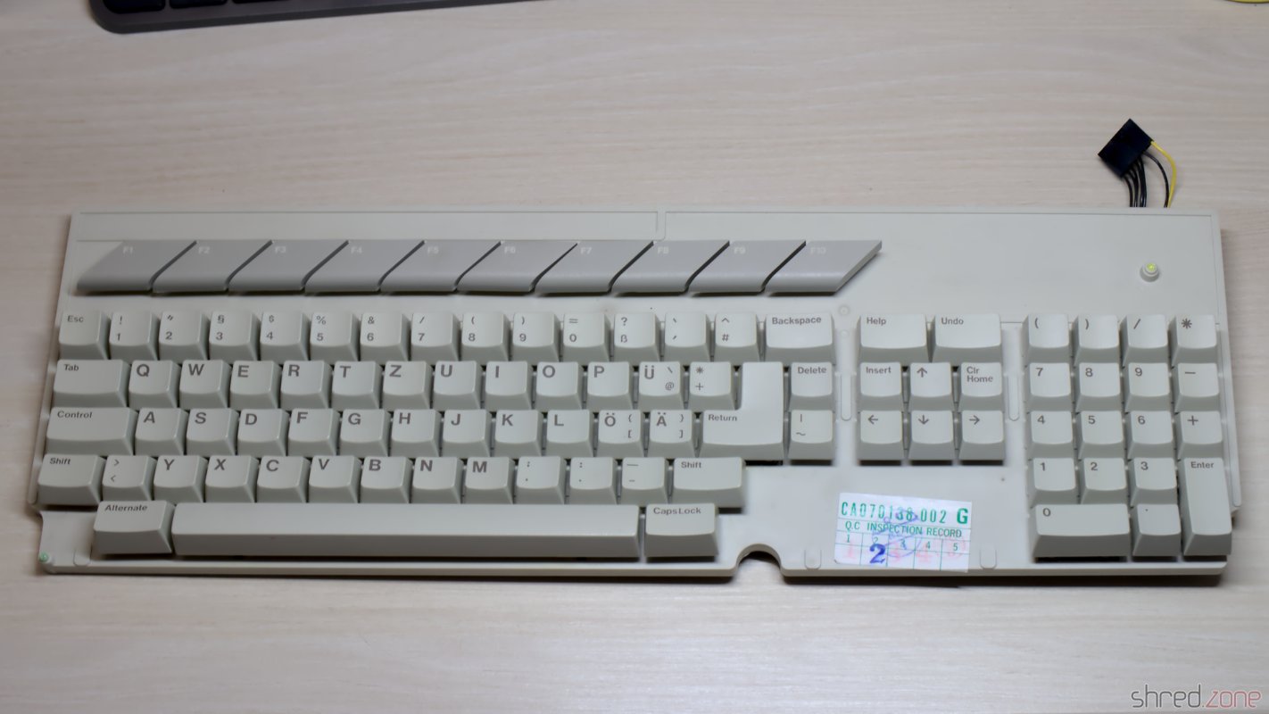
Even the keyboard wasn't really filthy, considering that the machine was in use for many years. It was still in for a thorough cleaning though.

The keyboard needs a cleaning. The keyboard's PCB, with the rubber domes. Cleaned keyboard. It looks much better.

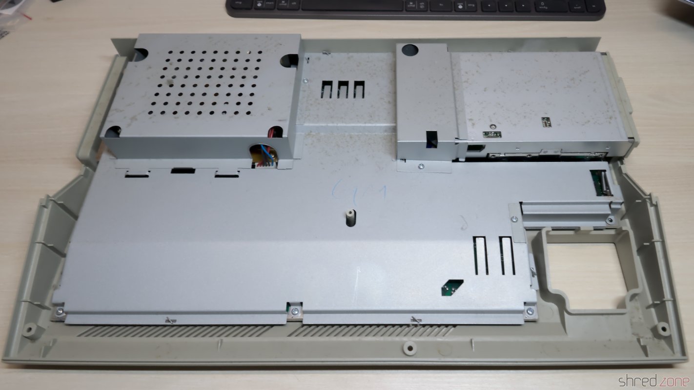
The Atari ST has an integrated power supply, unlike the Amiga 500 with its separate PSU on the floor. On the one hand, it permits to plug the unit directly to the mains. On the other hand, it makes the machine heavier, and makes modding more risky due to the presence of hazardous voltages inside the case.

WARNING: Switched power supplies may still contain high voltages hours after they have been disconnected from mains. I strongly advise against attempting repairs or modifications yourself. Please ask a trained technician for assistance!

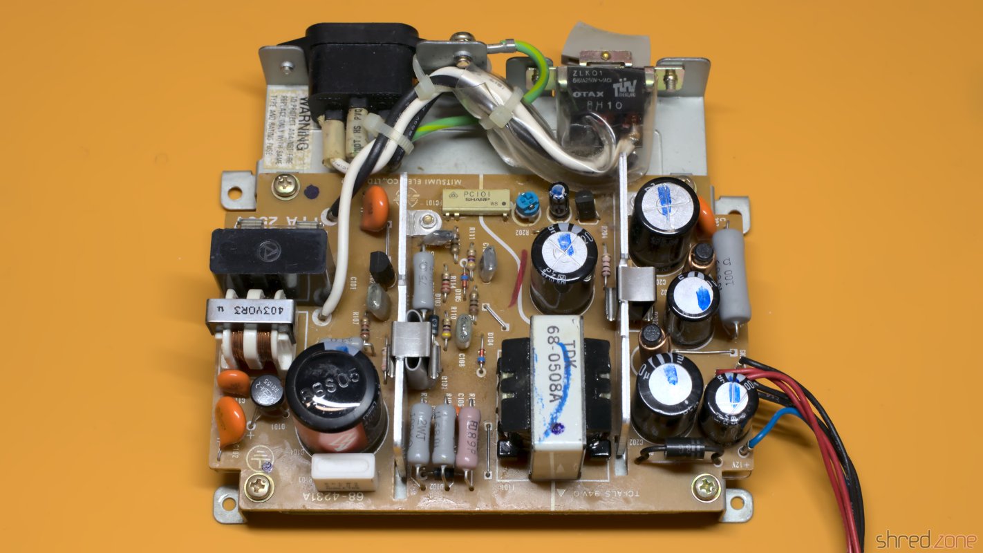
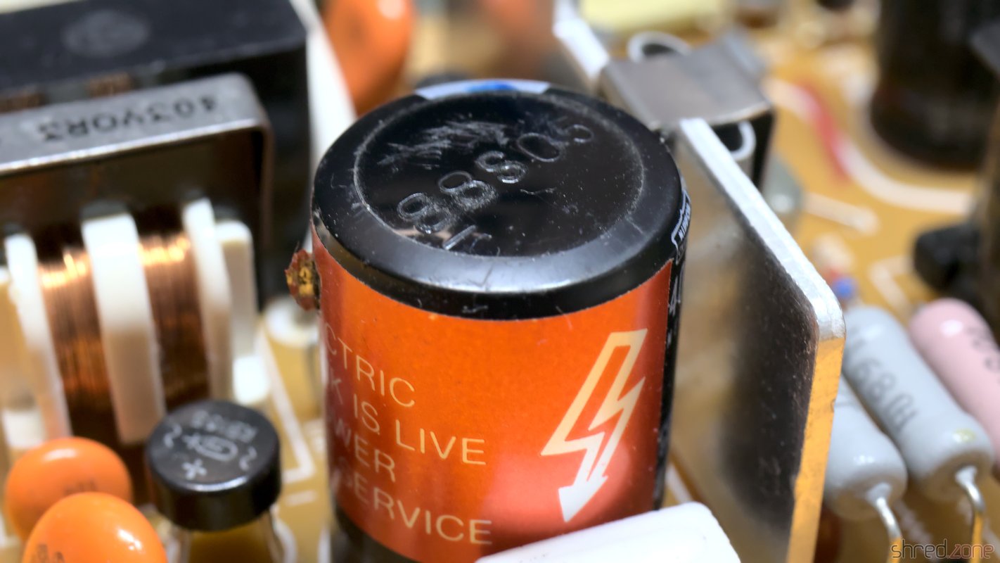
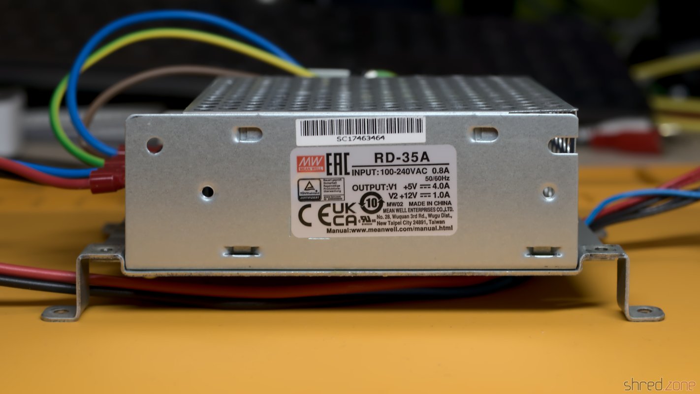
Inside my ST, I found a Mitsumi SR98 PSU. It looked okay, except of a bulged capacitor. However this type is said to be of poor quality, so I decided to replace it with a modern MeanWell RD-35A.

The original Mitsumi SR98 PSU. The filter capacitor is bulged.

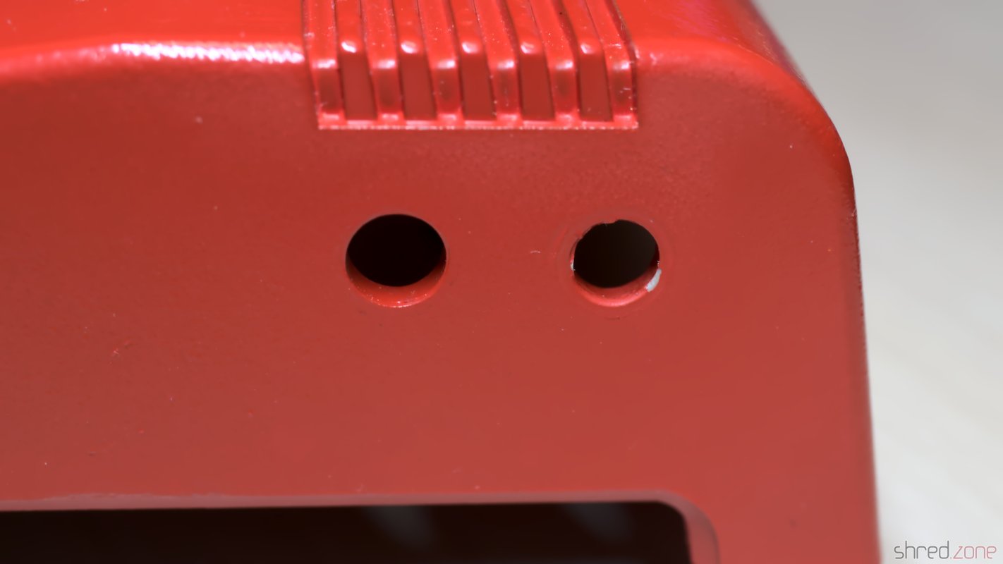
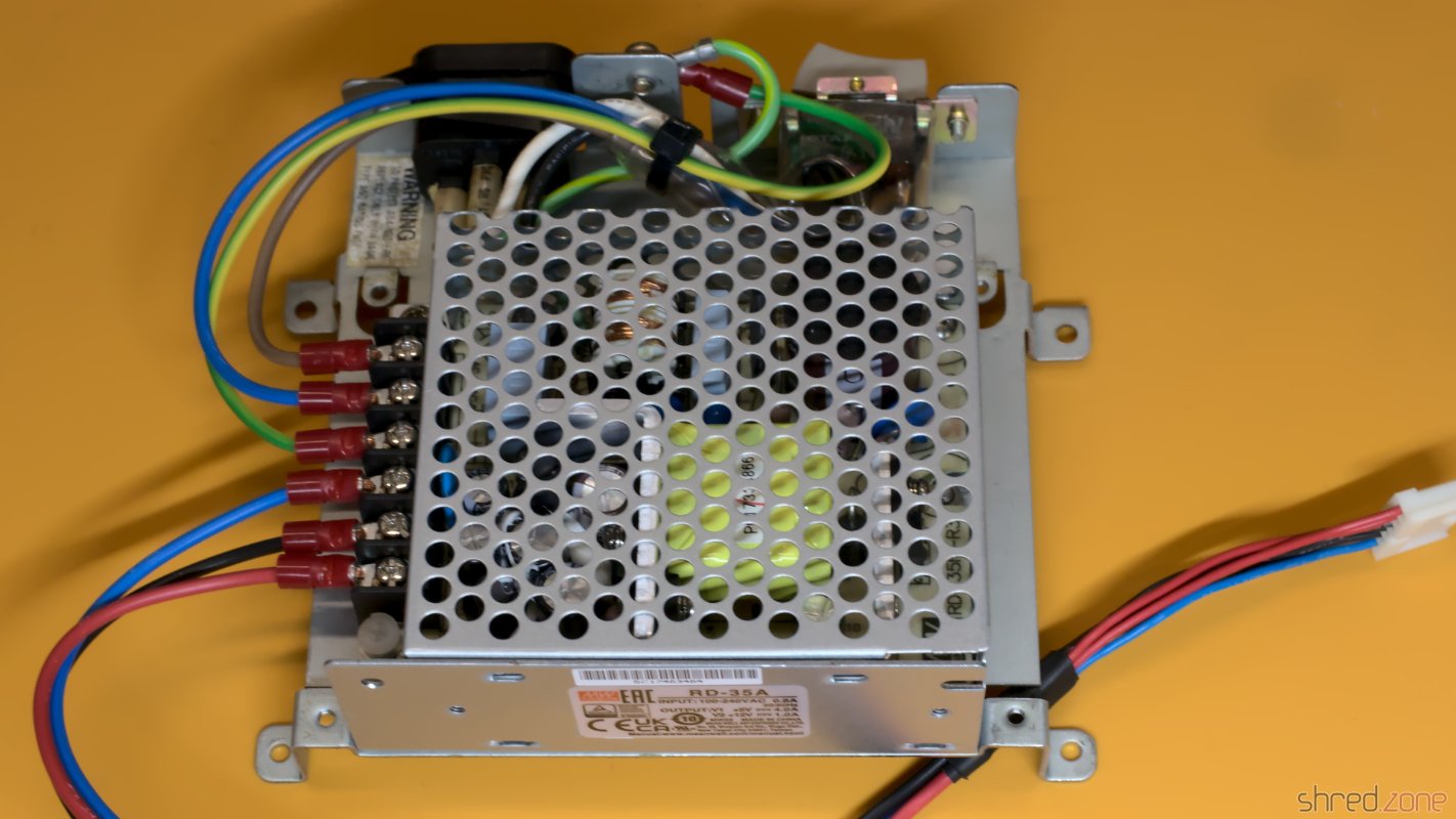
The MeanWell sits very nicely on the original frame of the Atari ST, almost as if it was made for that purpose. In order to mount it, I removed the original PSU and the insulator sheet below, and drilled two screw holes into the frame.

The terminals of the PSU can be either on the left or the right side. I decided for the left side, so the mains and mainboard power lines are cleanly separated and won't cross each other. I had to extend the wires to the mainboard for that, though.

I also took care that the PSU, the frame, and the shielding of the Atari ST are properly grounded. For that I had to add a ground wire from the metal frame to the ground terminal of the RD-35A.

A MeanWell RD-35A as replacement. Mains and output wiring is cleanly separated. It sits perfectly on the original frame. Wired properly. A terminal cover prevents touching the mains terminals.

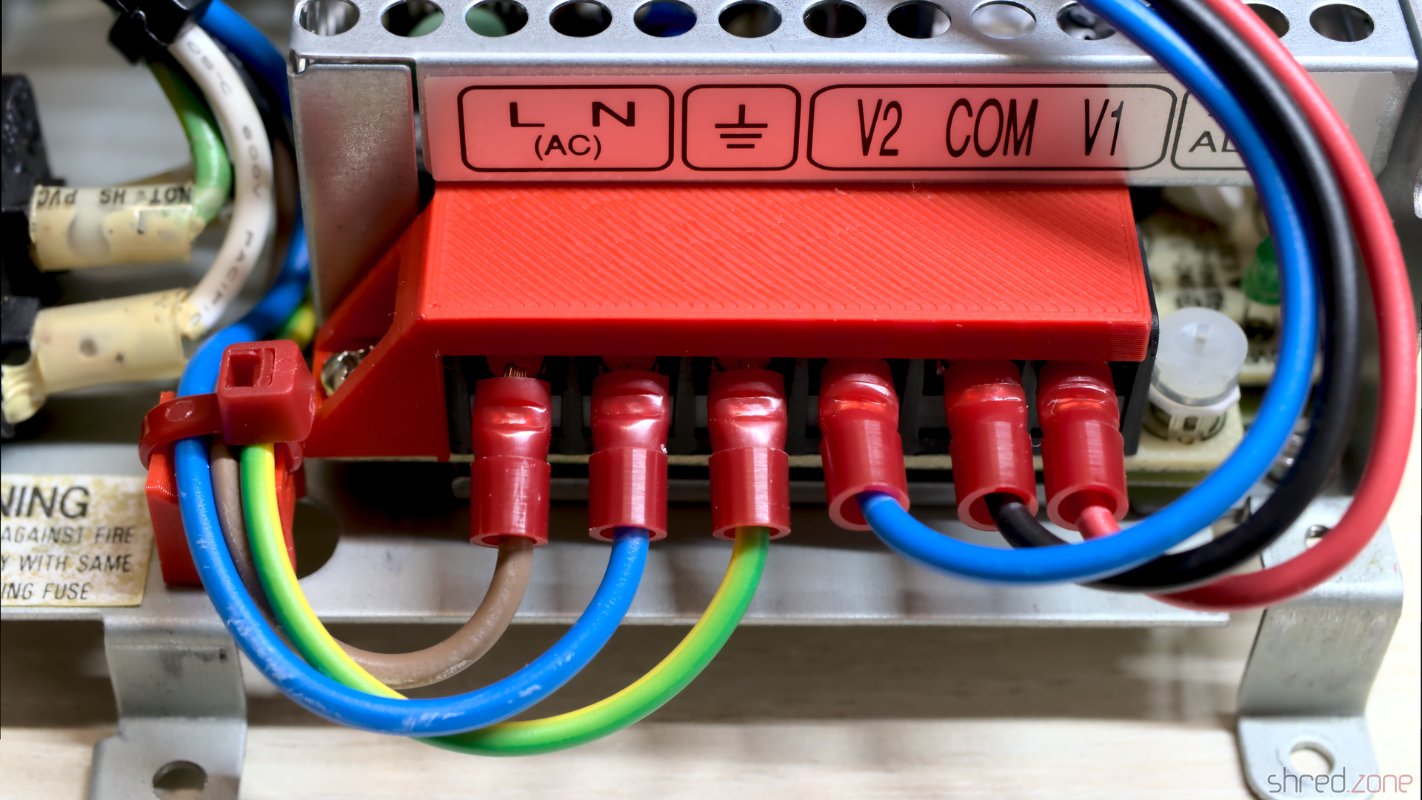
To be honest, I like this modification much better than the original open frame design. With a 3D printed terminal cover, all hazardous parts are now sufficiently protected against accidental touching.

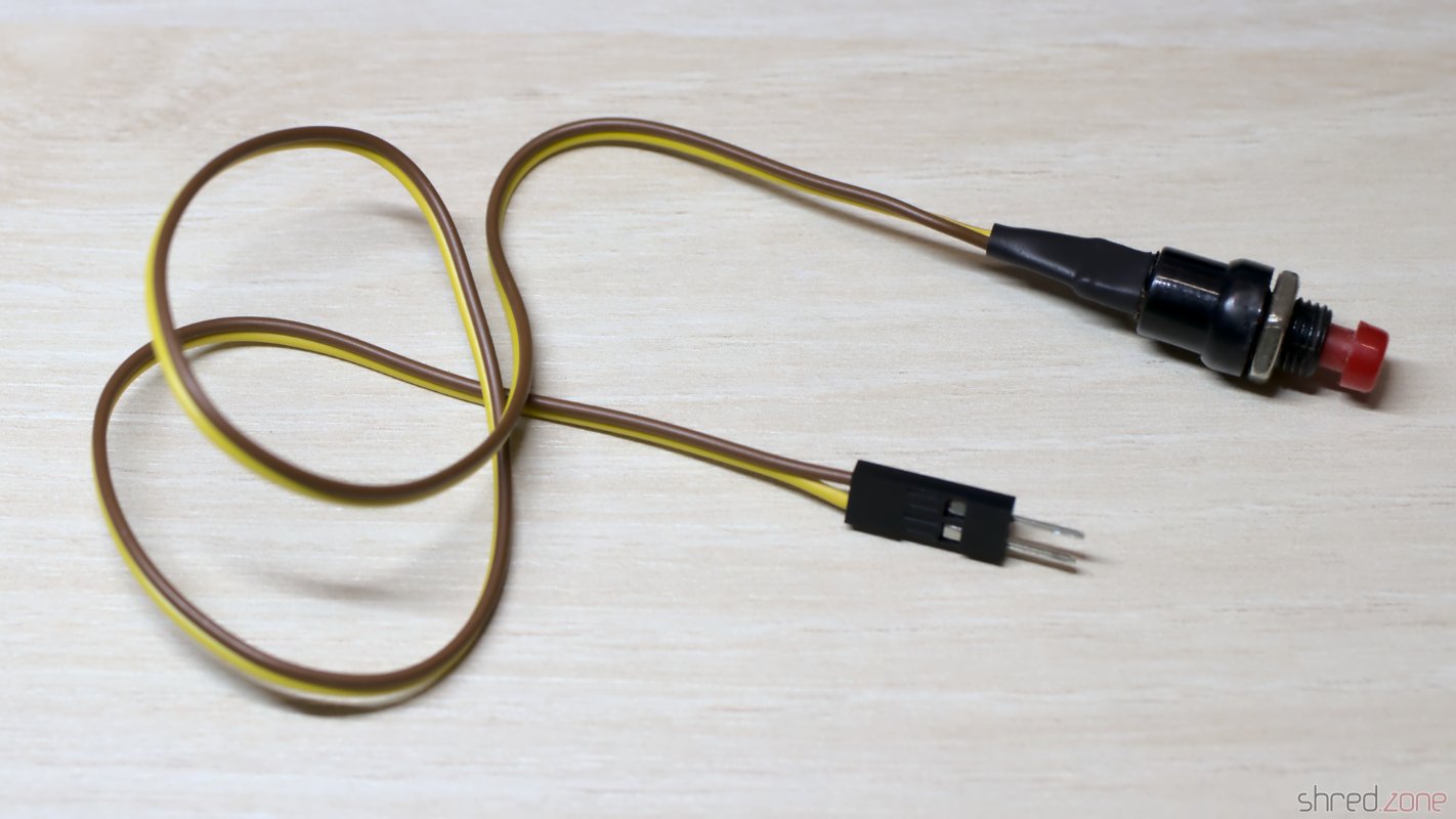
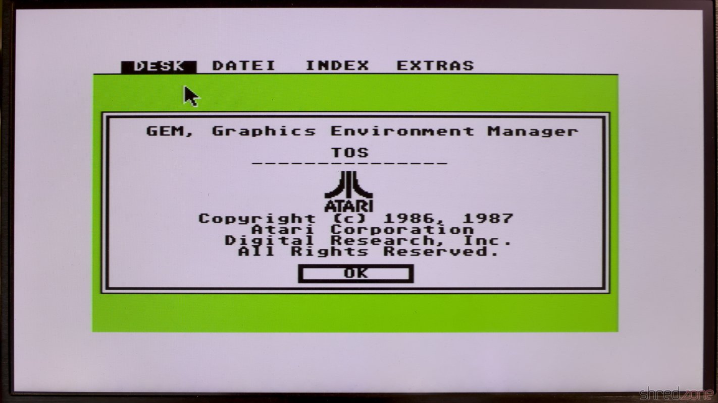
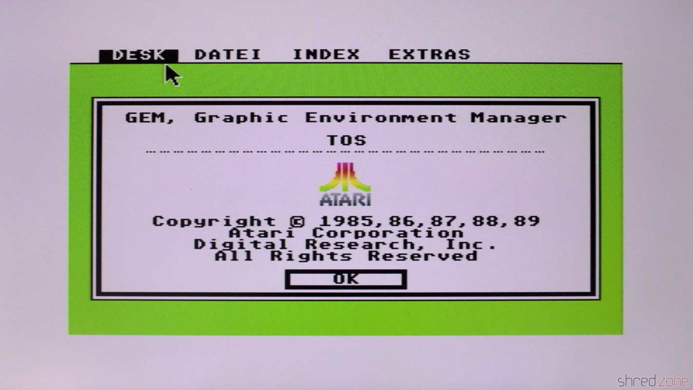
The machine was sold as "LED lights up, but otherwise untested". I usually refrain from using old and unrefurbished PSUs for testing, as they might damage the computer or might even explode in worst case. With the new PSU, it was now time for a first check if there are other damages. But I was lucky. The machine just booted up without problems. The only minor issue was that the Atari logo was black, which showed that the machine still had the original TOS 1.02 ROMs.

The about dialog, with a monochrome Atari logo.

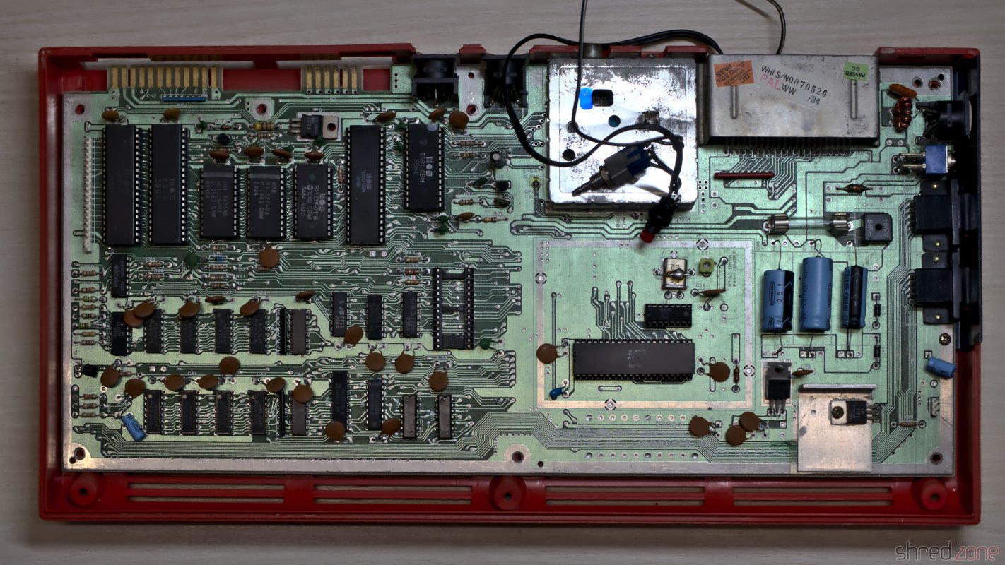
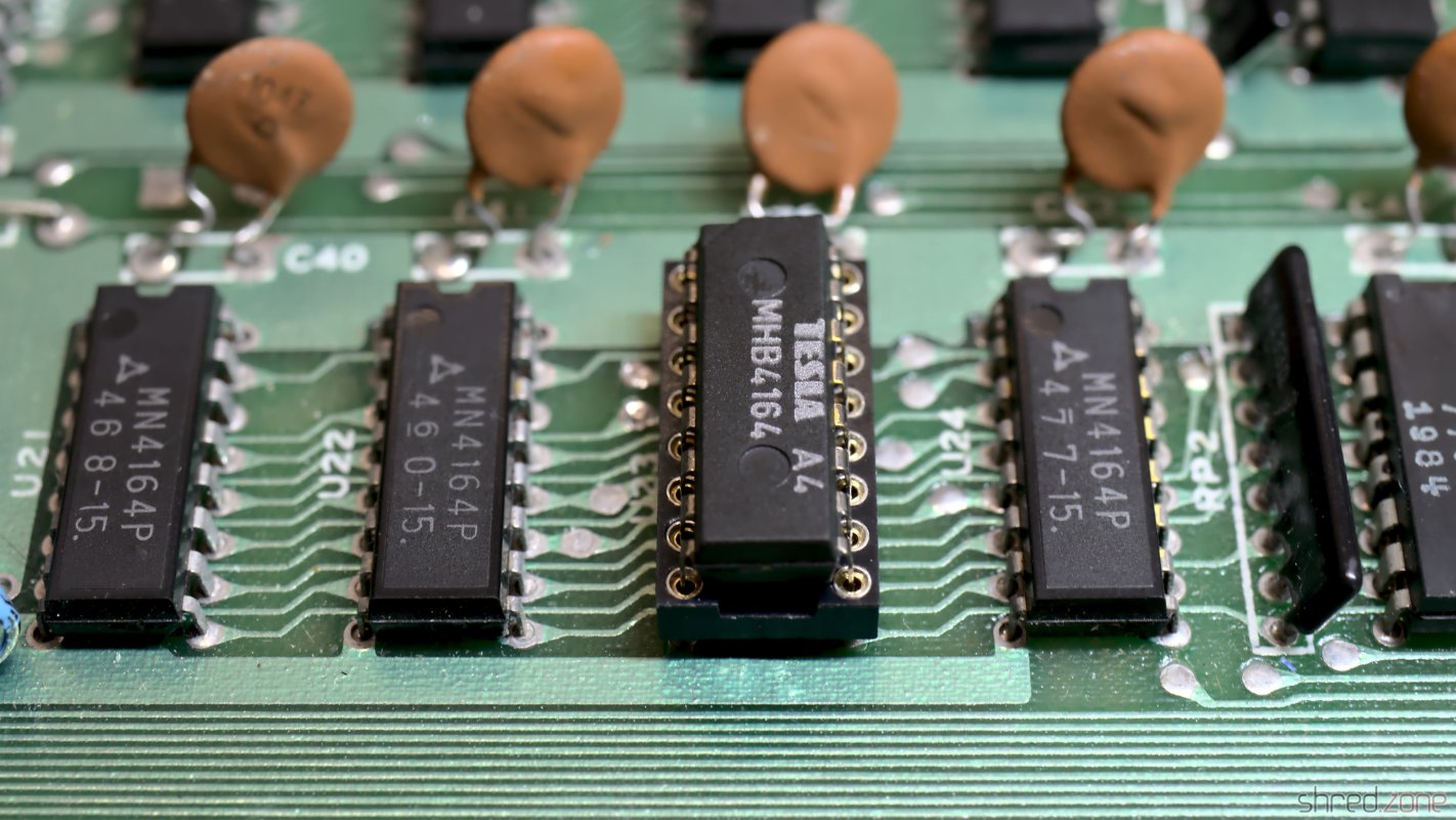
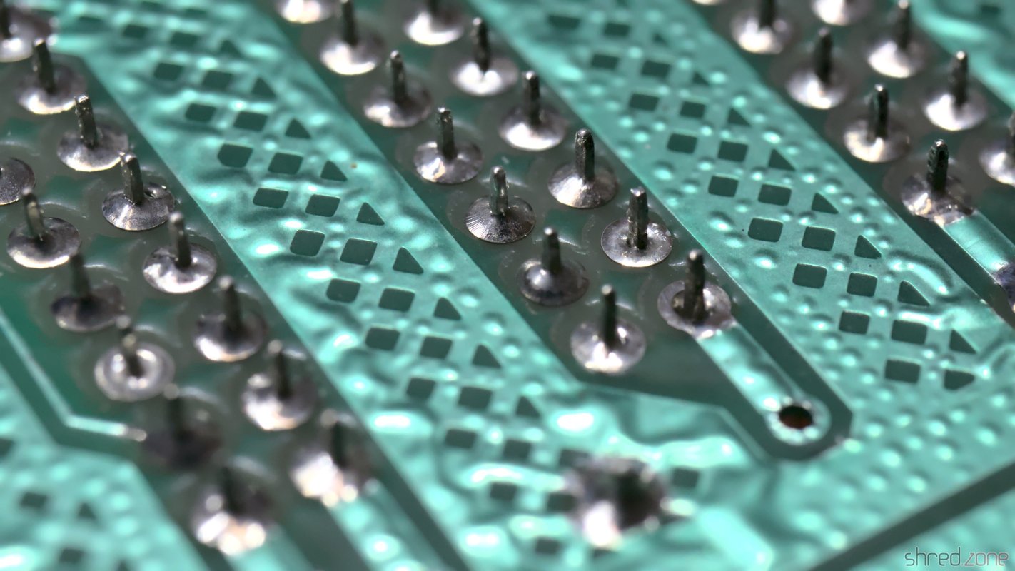
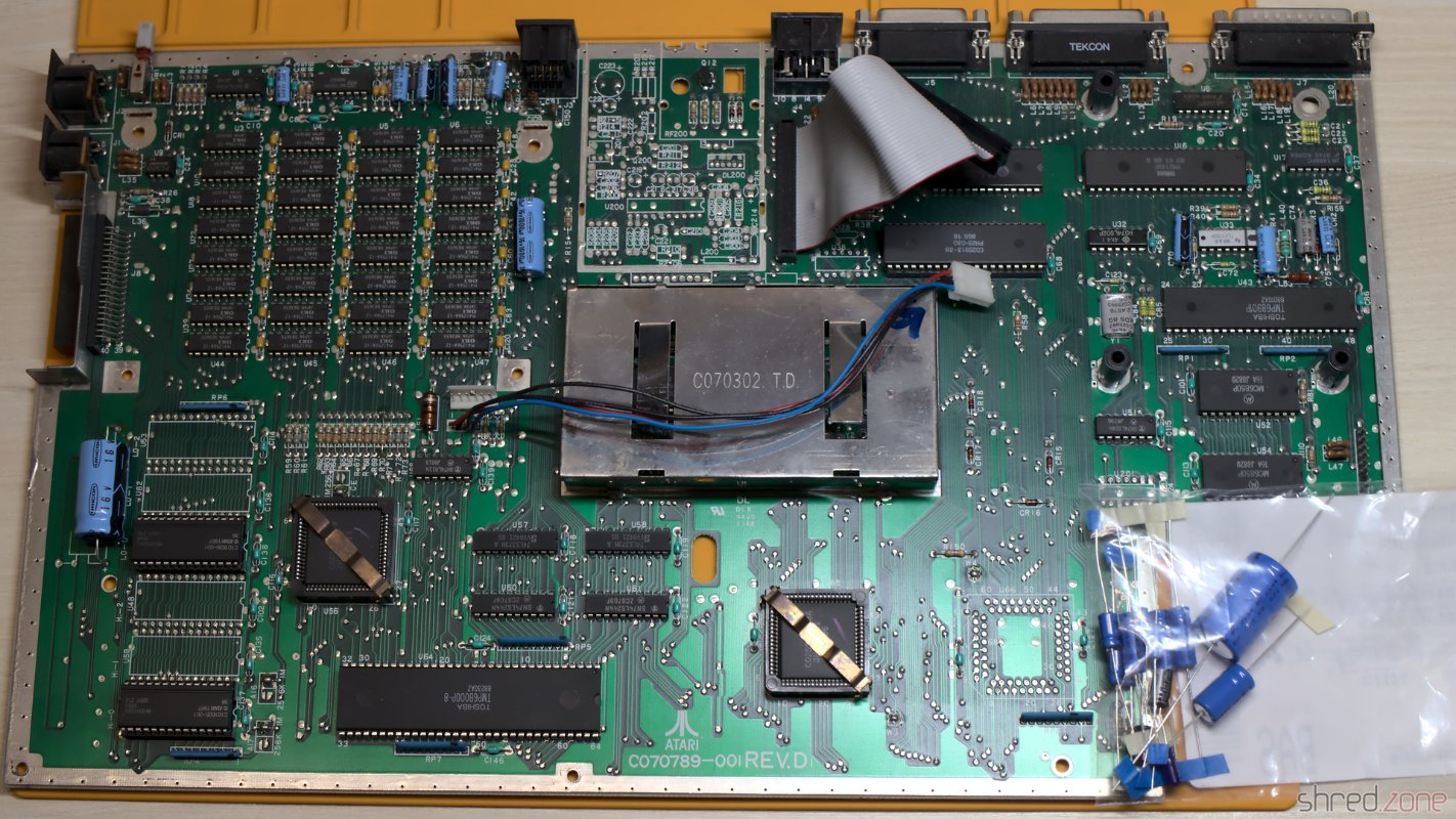
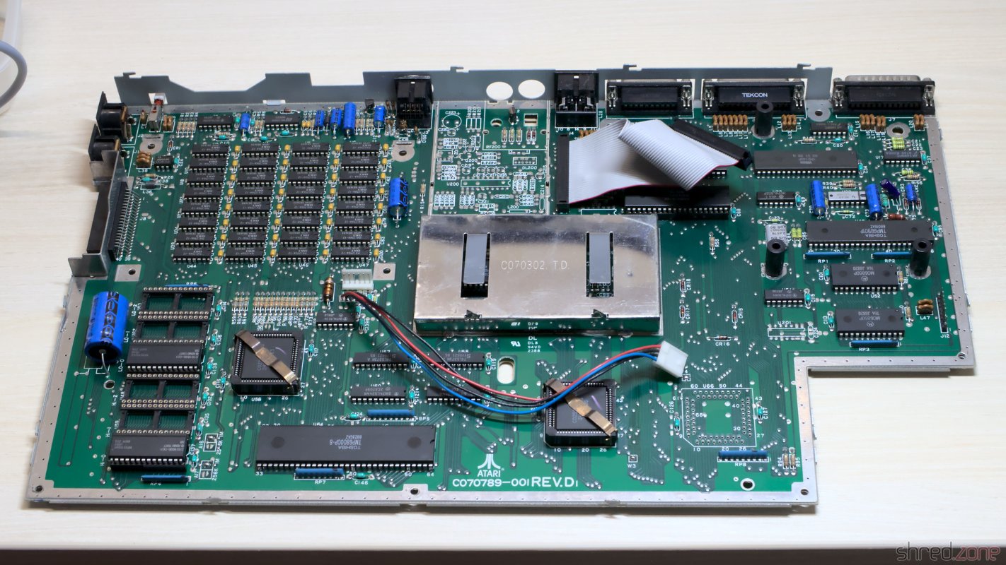
The TOS came in two strange 96KB ROMs. In order to do a TOS upgrade, I had to replace them with six (!) 27C256 EPROMs. This requires soldering in four more sockets, and changing three solder pads. But I was going to change the electrolytic capacitors anyway.

Time for recapping.

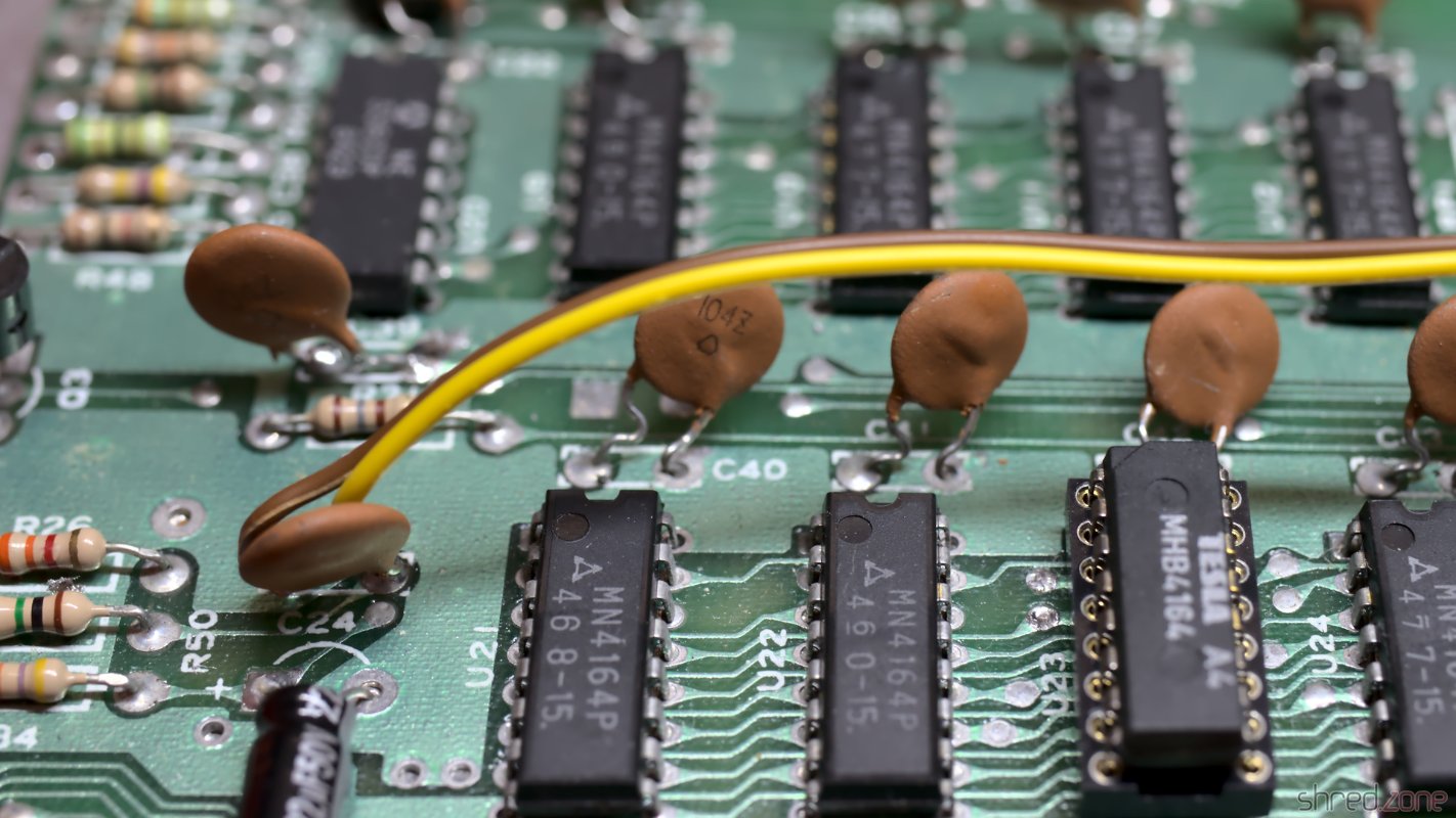
Recapping is a routine procedure for me when refurbishing home computers. Some people think it's not necessary unless one of the capacitors is actually bulged or leaking. However electrolytic capacitors also dry out over the years, and are losing their capacity. The result is that the system is still working, but might be unstable, or the audio and video quality might be degraded. The used components have usually been of a simple quality, since home computers were designed to be used for a few couple of years only, and production had to be cheap.

For soldering in the sockets, I first had to open the pads. Since I was on it, I also opened the pads for a Blitter socket as preparation for adding a Blitter chip. I no longer pursued this plan though after I found the prices of NOS Blitters. πŸ€‘ According to the feedback of Atari enthusiasts, the Blitter isn't really necessary anyway thanks to optimized CPU based routines. This is possible because, unlike on the Amiga, the Blitter is blocking the CPU during operation.

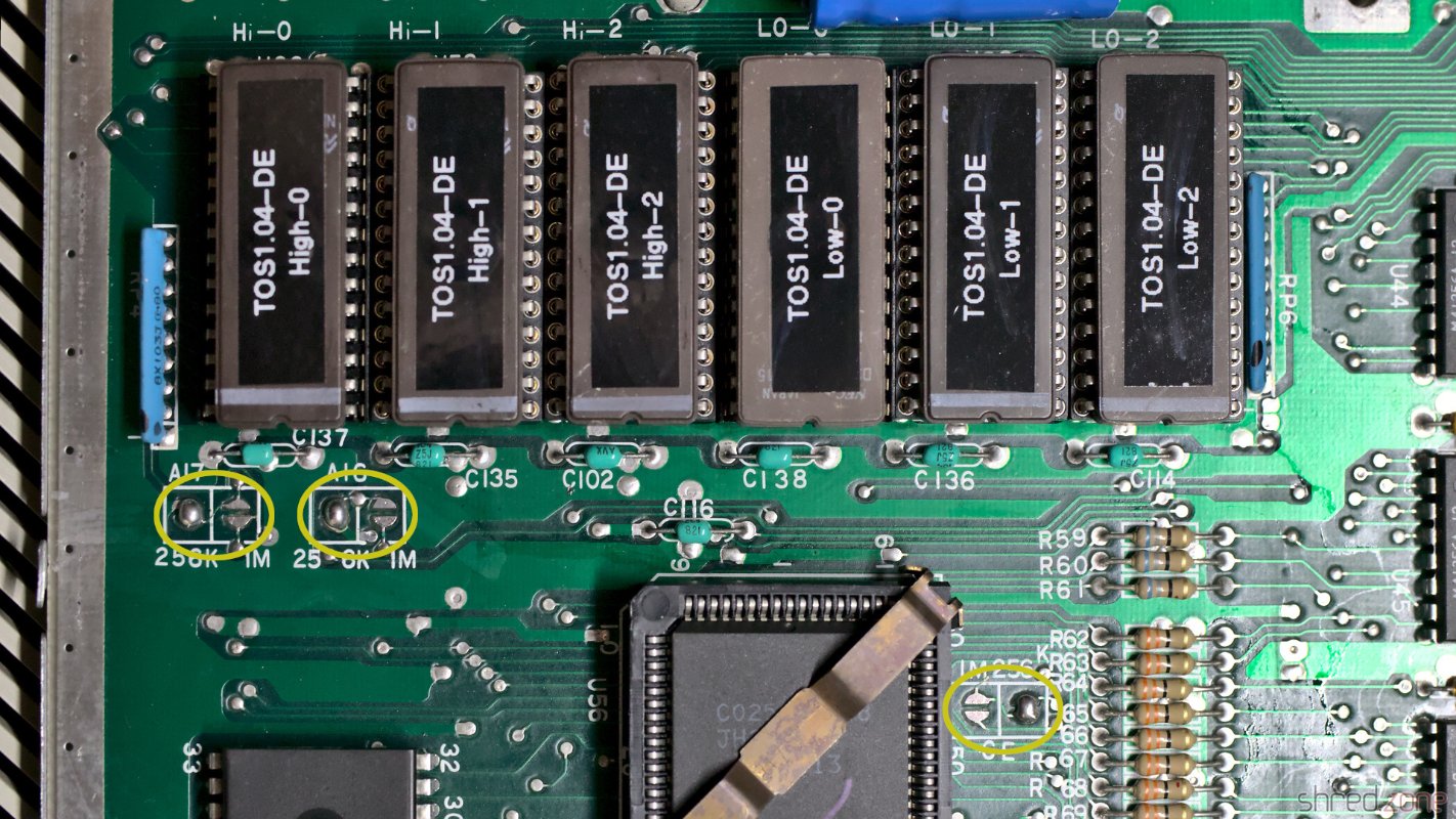
The Rainbow TOS 1.04 image was first split into an upper and lower half, and then each half was split again into three sections. I used my pynaroma tool for that, and then burned each section to an 27C256 EPROM, giving six EPROMs. When changing from two ROMs to six EPROMs, it's also necessary to set three solder pads from the "1M" to the "256K" configuration.

Recapping is done, and there are new sockets for the TOS EPROMs. Six 27C256 EPROMs. The three solder pads need to be changed as shown.

And that's it. The machine booted up again, and finally showed the Atari logo in rainbow colors.

Rainbow TOS 1.04

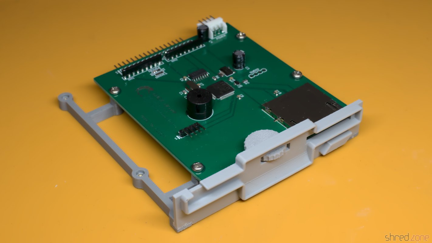
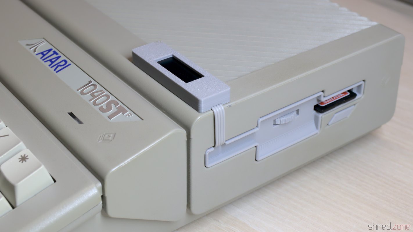
Since I never had an Atari ST before, I don't have any diskettes, and I'm also not too keen in making some. Fortunately Centuriontech GOEX drives are also available for Atari ST computers. It is a drop-in replacement for the original drive, but uses .st files on SD cards instead. The diskette file can be selected via an encoder and a tiny OLED display. The ST itself won't notice that there is no real floppy drive connected to it.

The floppy power cable turned out to be a bit too short on my machine, so I had to replace it with a longer one.

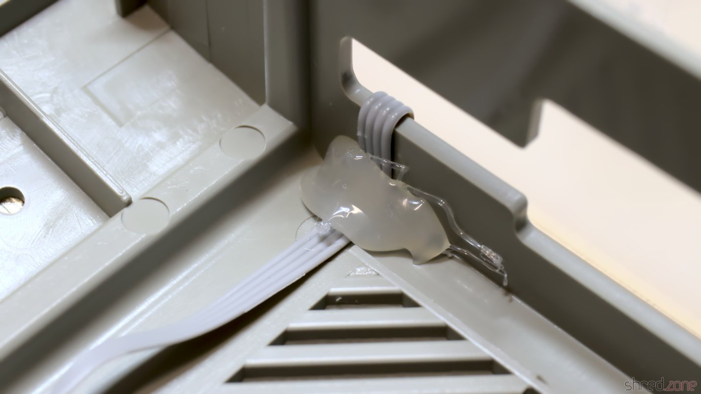
The OLED display is fixed to the case top with double-sided tape. The ribbon cable is then hot-glued inside, so it will sit nice and tight.

The Centuriontech GOEX drive. The OLED display cable is hot-glued on the inside. The cable will then sit nicely tight on the outside.

And that concludes the refurbishment of my new Atari ST. I'm happy to have it in my retro collection.

This is my refurbished Atari 1040STF.

Rehousing of a PSP

I was one of the fools who had backed the ZX Spectrum Vega+, in the hope to get a Speccy handheld console. The campaign was one of the biggest at Indiegogo, and ended in a disaster. The Vega+ has never been produced, and the funding money was gone after a year-long legal battle between the project initiators.

Later I learned that there has been a ZX Spectrum handheld console all the time: A Sony PlayStation Portable running a Fuse emulator. By a lucky chance, I was able to get a PSP now. It's a PSP-2000 in Ice Silver color, probably a self-import straight from Japan.

A PSP-2000 in Ice Silver.

Overall, it was in an excellent condition, except of some minor scratches on the display and the UMD drive door. The previous owner told me that the volume buttons were unresponsive, which was fine for me since replacement parts are still available. What he "forgot" to tell me though was that two case screws had been overturned in a repair attempt.

One of the two screws that have been overturned.

I tried a screw remover on them, but the screws were too tight and the screw heads were too tiny. After that, I tried to cut a slit into the screw heads, but they were too hard for that. Eventually I gave up, and (with a heavy heart) I just cut the case open.

No chance to remove them. I had to cut the case open. 😒

Rehousing

There are replica cases available from China, so I ordered a replacement in transparent blue. It came in a full set, with plastic clips, all the screws, springs, and even with fake labels for the serial number. The only parts needed for the transplantation are the hardware and everything related to it (like metal shieldings, or the LCD frame).

WARNING: Although the transplantation isn't really difficult, it still takes a bit of experience with this kind of hardware. There is a risk that parts might break, or that the PSP might not work any more after reassembly. If you plan to move your PSP to a new case, you are doing it at your own risk. Also, please take ESD precautions!

The first step is to tear down the old PSP. It's certainly a good idea to make detailed notes and photos that will help to find the correct place for each part later. Especially the UMD drive has a few small parts that turned out to be a bit tricky at the reassembly. The flat wires can be removed by either gently lifting or moving the black lever of the connector. Do not just yank them out. Never use force!

Display folded forward. Now I can start with the disassembly. Top half is emptied. Now for the bottom half with the UMD drive.

Disassembling the UMD drive was surprisingly easy. At some point the drive door needs to be taken out though, which requires a bit of force that made me feel uneasy. I was worried that the door or one of the hinges might snap.

In order to remove the WiFi antenna, the sticker in the battery compartment needs to be removed. I tried it with dissolving the glue with IPA, but it also dissolved the sticker. In retrospect, I better should have used a hairdryer or a heat gun.

And then it was done. The old PSP was disassembled, and all parts were scattered on my desk.

The PSP is completely torn down. Let's put the pieces of the puzzle back together.

The reassembly is done in reverse order. If you have made meticulous notes on the disassembly, it should be easy.

Although the replica set already contained many new case parts, I decided to reuse some of the original ones. The symbols of the direction and control buttons of the replica were printed on the top of the keycap, which looks considerably cheaper than the original parts which are printed on the inside. I also reused the shoulder buttons, the cover of the memory stick port, and the power slider.

The bottom side, with the UMD drive and WiFi antenna. The UMD drive door is still removed. Top side almost completely assembled again.

As one of the last steps, I could finally do what I originally intended to do only. I peeled off the old membrane of the control panel, and carefully put the replacement part on it. There are tiny holes in the holder and the membrane that helps to do a proper alignment.

This was what I initially planned: Changing the membrane of the control panel.

The rehousing was completed. In a last step, I cleaned the fingerprints off the LCD glass. I recommend to use a non-alcoholic LCD cleaner that does not leave streaks. I had used IPA first, but it dissolved the foam around the display and smeared it all over the panel.

The glass of the top cover was protected by two films (one inside, one outside) that needed to be removed. Then I used a camera lens brush to carefully brush off remaining dust particles and hairs from the glass and the LCD panel. Finally I closed the new case.

To my amazement, the PSP was still working! The new case doesn't look and feel as premium as the original case, but overall, the PSP looks very pretty in the clear blue case.

Transplantation was successful, and the patient is still alive.

Custom Firmware

My goal is to run emulators on the PSP. There is a lot of so-called "homebrew" software available, like emulators, tools, and even self-made games. But in order to run them, there must be a custom firmware installed first.

It's very easy to install it. First you need to make sure that the latest firmware 6.61 is installed on your PSP. If not, make an upgrade first. After that, a so called Infinity patch is installed. It takes care that the custom firmware is always active, even after a reboot. Finally, the custom firmware is installed, and then connected to the Infinity patch.

There is an excellent video by MrMario2011 that is explaning each step.

Homebrew software can be found just by searching for it. Of course, the first thing I installed was the ZX Spectrum emulator. It is based on the open source Fuse emulator. Games can be (legally) downloaded at World of Spectrum.

ZX Spectrum Emulator running the game "IK+".

There are many other emulators, e.g. for C64, Atari, Amiga, and many old game consoles. The Amiga emulator brought the PSP to its limit though. I tried to run the Red Sector Megademo on it, but it was quite sluggish and not really fun to watch.

Talking about demos: There are even a few demos for the PSP! One of the best voted is made by The Black Lotus (Amiga fans certainly remember the name of that group) and is open source. I recommend to run the version at GitHub, as the one at pouet.net might not run on the latest kernel versions. There is a video of the demo on YouTube (NSFW).

There are even demos for the PSP!

To wrap it up: While looking for software I felt like am too late for the party, as the PSP retro scene seems to have moved on already. Still, the PSP-2000 is a nice handheld console. And with the homebrew emulators, there is an almost unlimited pool of old retro games available.

MaestroPro Internal

MacroSystem Maestro Professional In the mid 1990s, MacroSystem Germany released the Maestro Professional sound card for the Amiga. It was a special sound card because it was fully digital, having only optical and coaxial digital connectors. It was suited for lossless recording from CD and DAT, as well as generating lossless audio output for DAT recordings. With tools like Samplitude, the Amiga became a studio quality digital audio workstation. There was also a tool for doing backups on DAT. At that time, these tapes were the cheapest way to backup entire harddisks (a 90 minutes DAT tape could backup almost 1 GB of data, which was a lot in the 1990s).

Unfortunately MacroSystem had never released a driver for the sound card, so it could only be used by a few (and mostly commerical) tools. I pestered their developers at every Amiga fair I could attend, but to no avail. Then, at the end of 1994, I decided to find the datasheets of the Yamaha chips, reverse engineer the board design, and write a driver myself. It took some time of trial and error, but eventually I was successful. In the coming years, my driver, the maestix.library (source code), became the inofficial standard driver. OctaMed Professional is maybe the most prominent software using it. Some professional music artists used Amiga and OctaMED for their production, so maybe my driver was even used for recording the masters of some famous CDs? 😁

Digital Audio in a Nutshell

The MaestroPro is able to receive and transmit digital audio data, either in the S/P-DIF or AES-EBU standard. The former one is still widely used in home equipment today, while the latter one was rather common in studio equipment. Today's standards permit different encodings and high sampling rates, but the MaestroPro could only read 2-channel 16-bit raw audio with sampling rates of either 48kHz (DAT), 44.1kHz (CD), or 32kHz (DAB).

Besides the raw audio data, the standard also transports Channel Status Bits (CSB) and User Data Bits (UDB). The CSB contain information like the used sampling rate and the copy prohibition state. The UDB are not standardized, and usually transport proprietary data between studio equipment.

Inside the Maestro

The board's design is straightforward. It mainly contains a transmitter, a receiver, and FIFO memory for transporting the samples between the board and AmigaOS.

Receiver
YM3623B DIR
Receiver...
Transmitter
YM3437C DIT2
Transmitter...
Serial to Parallel
Serial to Parallel
Parallel to Serial
Parallel to Serial
R-FIFO 1Kx16
R-FIFO 1Kx16
T-FIFO 1Kx16
T-FIFO 1Kx16
DATA BUS
DATA BUS
Board
Controller
Board...
UDB Shift Register
UDB Shift Register
Sampling Clock
Sampling Clock
48kHz
48kHz
Optical
Optical
Coax
Coax
Optical Out
Optical Out
Input Signal
Input Signal
FIFO
FIFO
Bypass
Bypass
In
In
Source
Source
UDB Data
UDB Data
Text is not SVG - cannot display

The optical and coaxial inputs go to a Yamaha YM3623B Digital Audio Interface Receiver (DIR). This chip decodes the audio data stream, extracts the CSB and UDB, and generates a raw bit stream of the audio samples. Shift registers convert it to a 16 bit parallel stream, which is stored in a 1K x 16 bit receiver FIFO. As soon as the FIFO is half filled, an interrupt is raised, and the Amiga driver reads the received data from the FIFO. This happens up to 190 times per second.

The most important CSB are readable via a status register of the board controller. The UDB are copied to a separate 8 bit shift register, which could be polled by the driver. However, UDB are usually 32 bit wide, so reading them was never really used in practice (at least not to my knowledge). The Maestix driver only provided a very rudimentary API for the UDB.

On the transmitter side, the 16 bit samples are pushed to a transmitter FIFO, and then converted to a serial bit stream by shift registers. A Yamaha YM3437C Digital Audio Interface Transmitter (DIT2) converts it to a digital audio stream and sends it via an optical output. The Maestro Pro does not have a coaxial output, presumably because there was not enough space on the board for a fourth connector.

The DIT2 is unable to generate the sampling rate clock by itself. It needs an external clock source instead. On the Maestro Pro, this clock is generated by the DIR. It is either derived from the bit stream of the selected input, or generated by an internal fixed 48kHz clock source. For this reason, the Maestro Pro needs to rely on external signal sources for 32kHz and 44.1kHz output sampling rates.

The transmitter can choose from two data sources. One source is the transmitter FIFO. The other source is the bit stream from the DIR, bypassing the FIFOs. This enables the board to modify the UDB and CSB of the incoming signal directly, without involving the CPU. But since the transmitter and reciver paths are fully separate, the MaestroPro is even capable of providing full-duplex audio streaming. The maestix.library takes advantage of that with the "realtime FX" feature, where the signal is read from the receiver FIFO, modified by the CPU, and then immediately sent back to the transmitter FIFO.

The entire board is controlled by three GALs and a small handful of 74LS logic chips. They take care of the Zorro bus protocol, provide mode and state registers, and orchestrate the transmitter and receiver paths.

Broken MaestroPro

All of the components of a MaestroPro can still be found on the market, although both Yamaha chips are not produced any more and can only be found on some Chinese online markets as NOS parts. But basically, it is still possible to repair a broken MaestroPro.

The major weakness are the three custom programmed GALs. The GAL manufacturer states a memory retention time of about 20 years. It sounds like pretty much, but remember that these boards are almost 30 years old now. We already exceeded that life span by 50%!

When I reactivated my Amiga in 2021, my MaestroPro was working fine for a couple of minutes, but then it started to lose synchronization with the audio source. The only way to fix that problem was to turn off the Amiga and let it cool down for several minutes. A deeper diagnostics showed that the card seemed to detach itself from the Zorro bus. It seemed that one of the GAL chips had thermal problems, or was maybe starting to "forget" its programming. Fortunately I was able to recover the programming scheme. I replaced the original GALs with brand new Atmel ATF16V8C-7PU ones, and to my relief, my MaestroPro is now working stable again.

The fusemaps are copyrighted by MacroSystem, so I am not permitted to share them to the public. However, if you happen to have a broken Maestro Pro, please get in contact with me. Maybe I can help you to repair it.

The Maestro (without Pro)

There was a predecessor of this board. It was just called "Maestro", and had some major drawbacks. First of all, it had no transmitter and could only receive audio data. Secondly, it did not have a FIFO, so the sample words had to be read by the CPU as soon as they became available, which is up to 96,000 times per second. This was only possible by turning off multitasking and interrupts during recording, which also meant that recordings could not be written to harddisk, but had to be stored in RAM first.

Compared to its successor, the Maestro hasn't been a great success. I haven't seen one since the end of the 1990s, and I also don't know a single software that is actually using it. Due to the technical limitations, the Maestix driver won't support it.

The Red C64

My first home computers were made by Sinclair, and I liked them. Then one day, my brother brought a Commodore 64 that he had borrowed from a classmate. He showed me a demo called "Trap", and I was flabbergasted about the sound abilities of the SID chip. My ZX Spectrum just had a plain beeper, and since then I wished Sinclair had added a decent sound chip. Or that I had a C64 instead of the Speccy.

35 years later, this wish came true as I bought my first C64. It came in a case that is painted in a bright red color. It was sold as broken. The PLA chip was missing, and there was no way to test if that was the only problem.

The machine arrived here in a pretty good state. The paint job was actually quite well done, and everything was nice and clean. It certainly wasn't much used after the previous owner did the modification. I also found traces of further planned modificiations, like numbers painted on the PCB. Maybe the machine broke during their modification attempt, ending their endeavor.

Let's have a look inside. There is a 250425 mainboard, and the PLA chip was missing as announced. I also found that all other chips were made in 1984, except of the VIC which was made end of 1985. This might be a bad sign, maybe they swapped the good VIC with a broken one before selling the machine.

Inside there is a 250425 mainboard. The PLA chip is missing.

I first powered up the board and checked the voltages. The +5V and +12V were fine, so I could be sure that I wouldn't damage the replacement parts I was going to put in.

For the missing PLA, there is a choice of modern FPGA based replacements. I chose a PLAnkton, which just fits into the socket and even has about the same color as the main board. After that, I connected a monitor and powered up the machine again. I got a video sync, but the picture was black. Uh oh… Is it the VIC?

A C64 Dead Test cartridge quickly gave a hint. It flashed the screen four times, saying that the U23 DRAM chip was broken. Fortunately these are 4164 type 64Kx1 DRAM chips, like they are also used for repairing ZX Spectrums. I have a few of them in stock, so I could just replace it.

One RAM is replaced. It's the same type that is used for ZX Spectrum repairs.

Next test, and this time I finally got the famous blue READY prompt. A full diagnostics run confirmed that the missing PLA and one DRAM chip was all that was broken.

Everything is fine now! πŸ˜€

The board is now working again, and ready to be futureproofed. First I replaced the electrolytic capacitors. For C13, I used a bipolar capacitor, which (in my opinion) gave an audible enhancement to the SID audio quality. The old 78xx voltage regulators were replaced by Traco Power DC/DC converters that won't need heatsinks. What got heatsinks instead were the CPU, SID, and VIC. The PLA should get a heatsink as well, but the PLAnkton replacement only consumes a fraction of the original PLA power and stays cold.

I also found four MOS-77xx chips on the board. These are standard 74LS chips, but they are notorious for their high failure rate. I preemptively replaced them with their standard counterparts. The mainboard should now be fine for the next twenty years.

The refurbished board, with PLAnkton, heat sinks, new caps, and DC/DC converters.

The keyboard was in a very clean state, but anyway I decided to disassemble and wash it. I pulled off all keycaps and cleaned them in an ultrasonic bath. I also removed the back PCB, and cleaned the plungers and contacts with a bit of IPA. After that, I reassembled the keyboard. For the space key, I put a bit of silicone grease on the lever mechanics, which gave a much more quiet and satisfying sound when the space key is pressed.

Keycaps put back to their place after washing. The cleaned keyboard.

The previous owner added two extra buttons to the right side of the case. One button is a reset button, a standard modification on a C64. The other one was connected to the "bus available" pin of the expansion port. It essentially freezes the system as long as the button is kept depressed. I have no use for a freeze button, so I decided to put the reset button back, but leave the freeze button out.

I connected the reset button to C34 instead of the expansion port. When pressed, it will retrigger the reset monoflop by discharging the capacitor. This way the button is debounced, and the reset signal is kept for an appropriate minimal time. (C34 applies to 250425 boards only, for other versions see their schematics! Also make sure you're not accidentally shorting one of the decoupling capacitors.) I used Dupont connectors to make the reset button detachable from the mainboard, in case I want to remove the top shell again.

The reset button can stay, but got a Dupont connector so the upper shell of the case can easily be removed. The reset button is connected to C34.

To close the hole of the former freeze button, I was quite lucky that the case was painted in RAL 3020 "traffic red". I found that I have filament in the same color, and 3D-printed a small plug that was then hot-glued to the case. The hole is still visible, but it looks acceptable now.

The holes made for the reset and the freeze button. I don't need the latter one anymore. The reset button is back in its place. The freeze button hole is now closed with a 3D printed plug.

And that's it! I finally have my own, red C64!

Welcome, my shiny new Red C64! 😍

ZX Spectrum "Portugal"

And yet another Speccy that I could buy for a good price. The seller said it was "untested", but I allege that he knew very well it was broken. It's fine for me as I mainly buy those things for the repair fun. 😁

The computer was in a sad condition when I got it. What's remarkable is that the machine was "assembled in Portugal". It's the first time I see this, and to be honest, it was one of the reasons why I wanted to have it. According to the very few information I found on the internet, those machines were intended for the Portugese and South American market, but some of them also made it to the UK and other European countries.

The faceplate was heavily bent, and a connector of the keyboard membrane was broken off. It seems that the previous owner tried to replace the membrane, but wasn't able to remove the faceplate.

The new Speccy is in a poor condition. One of the membrane connectors was broken off and missing.  It was assembled in Portugal.

That's the first hint that the machine wasn't "untested", but underwent a botched repair attempt.

I got the second hint when I tried to power up the machine, but found that it was completely dead, with all the voltages missing. The 5V is generated by an 7805 voltage regulator. It could just have died of old age. But considering the other hint, I rather guess that the previous owner has tried to power this machine with a standard 9V power supply. It has a reversed polarity, which kills the 7805 instantly, and usually damages the lower RAM chips and other components.

Let's have a look inside. There's an Issue 6A board inside, which is the final revision of the board. But besides that, there were no surprises. Anyway it's the first Issue 6A board I own, so I'm happy to have it.

An Issue 6A board, probably built around end of 1984.

The 7805 regulator is definitely broken, but I would have replaced it with a Traco Power DC/DC converter anyway. After I replaced it, the 5V line was back. To my surprise, the 12V and -5V lines were also back, so at least there was no further damage to the power supply.

I did my usual composite mod. Then I connected the computer to my monitor and powered it up to find out what else is broken. To my surprise the start screen appeared, and the Diag ROM also found that all RAM chips are working.

The Speccy just booted up. The Diag ROM found no further defects.

Okay, so much for the "repair fun" I was hoping to get. On the other hand, this board has a second custom chip, the ZX8401, also known as ZXMUX chip. If it would have been damaged, repair would have been a lot more difficult. Not impossible though, since the ZXMUX can be simulated by a few standard SMD chips.

Now that the Speccy was repaired, I continued with replacing the electrolytic capacitors. I also found and fixed a lot of cold joints at the lower RAM chips. The refurbishment of the board was completed after that.

The board after repairing and recapping. A lot of cold solder joints.

Let's have a look at the case. The membrane connector was broken, but luckily there are new membranes available at retro shops. The previous owner tried to remove the faceplate, which is most often glued to the case. Most often, but not here. On this computer, the faceplate was just held in place by four brackets. All that would have needed to be done was to open these brackets and then easily pull of the faceplate.

The faceplate is held by four brackets that can be easily seen on the inside. All that needs to be done is to open them. The faceplate itself is not glued to the case.

Sadly, thanks to the botched repair attempt, the original faceplate was bent too much to be recoverable. It also had some visible scratches. I wished I could have salvaged it, but I decided to replace it with a new one instead. This time I took a metallic red faceplate, which looks as hot as a sunset in Portugal. πŸ˜‰

My new ZX Spectrum "Assembled in Portugal".

And there it is, another ZX Spectrum for my collection.