Candle at the Pool

Sidecar Restauration, Part 3

In the third and final part, I am going to futureproof the Sidecar and finally test it. Will it work after all the hours and patience I put into the repair?

Gotek Drive

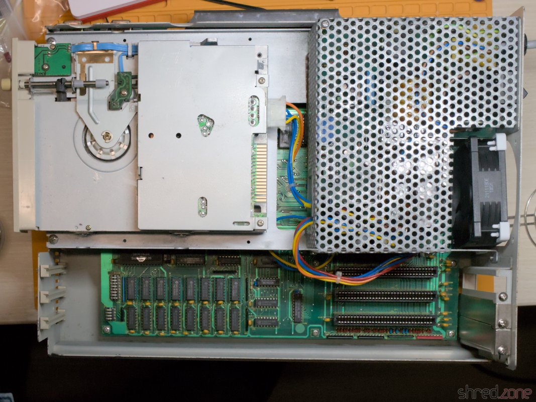
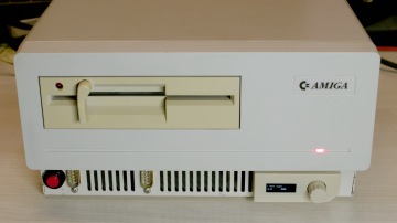
I probably only own a single 5¼" floppy disk, back from my time at school. However the Sidecar won't do much without floppies, so I decided to add a Gotek drive.

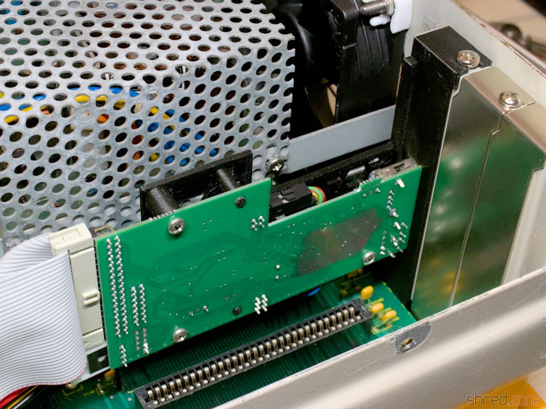
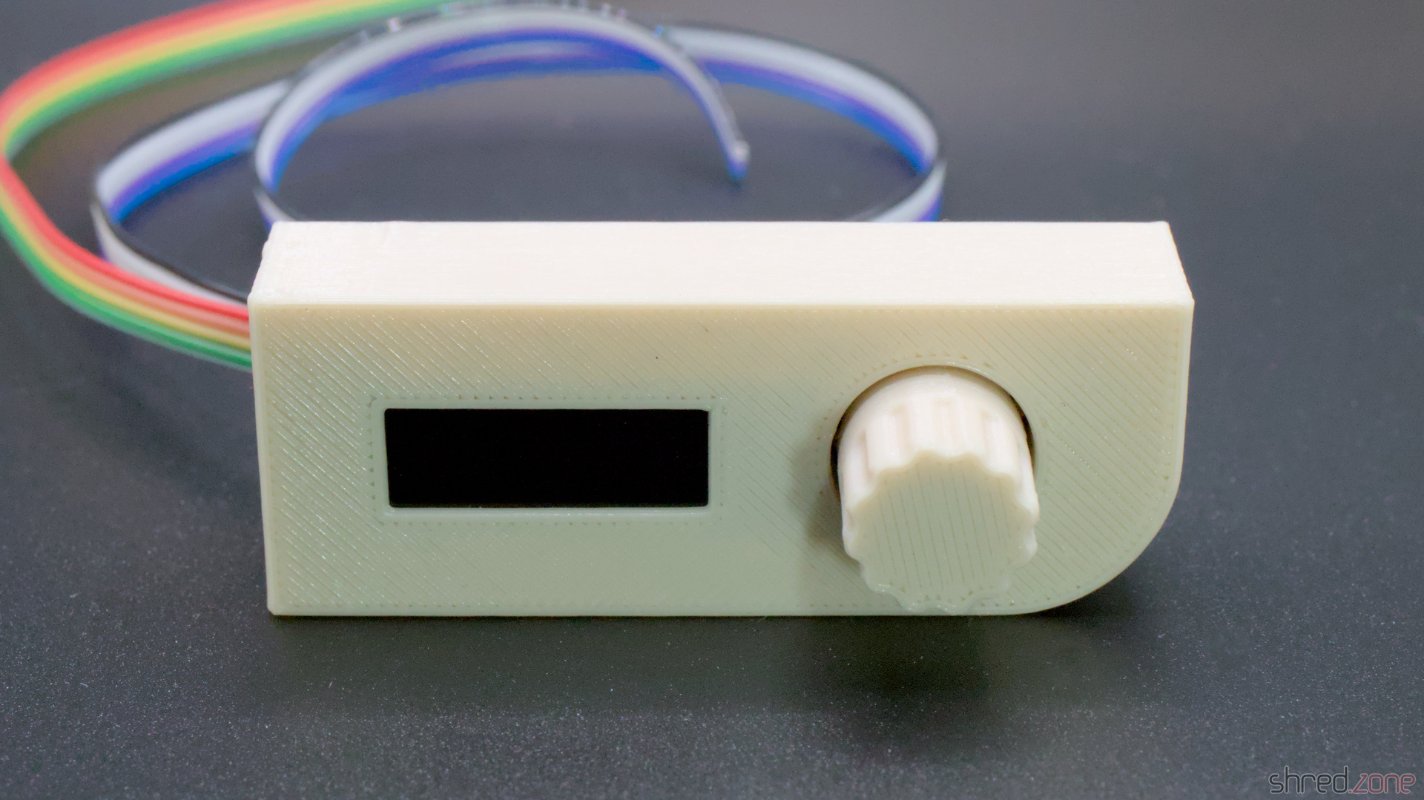
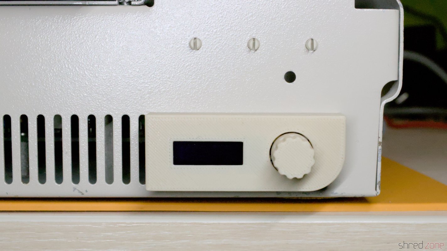
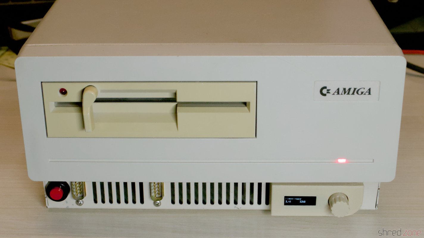
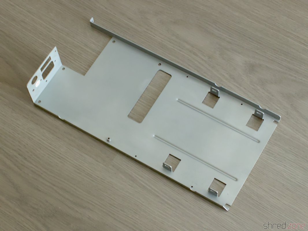
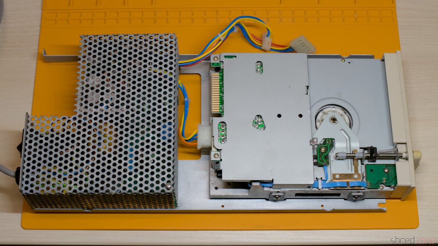
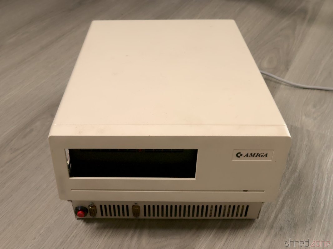
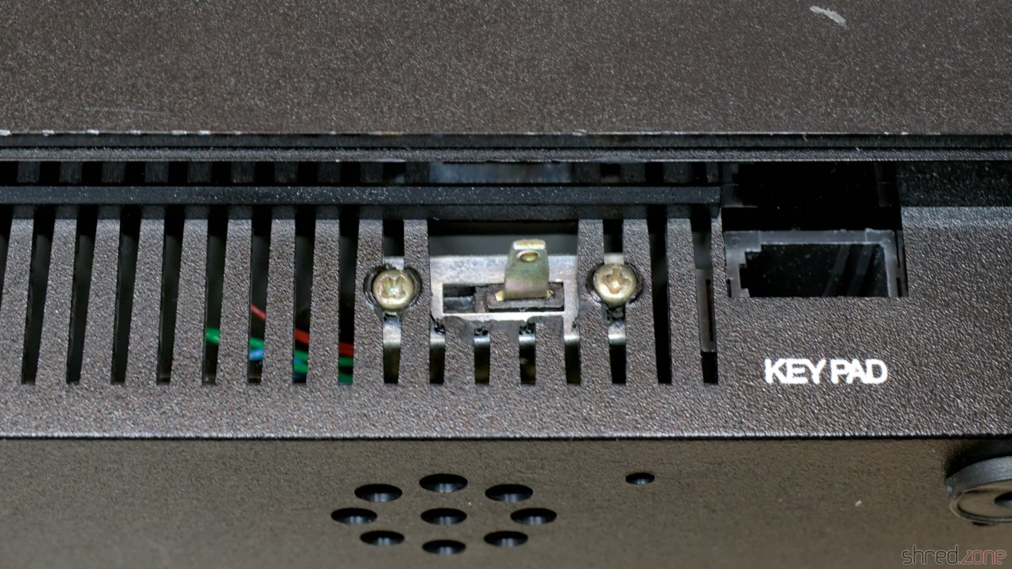
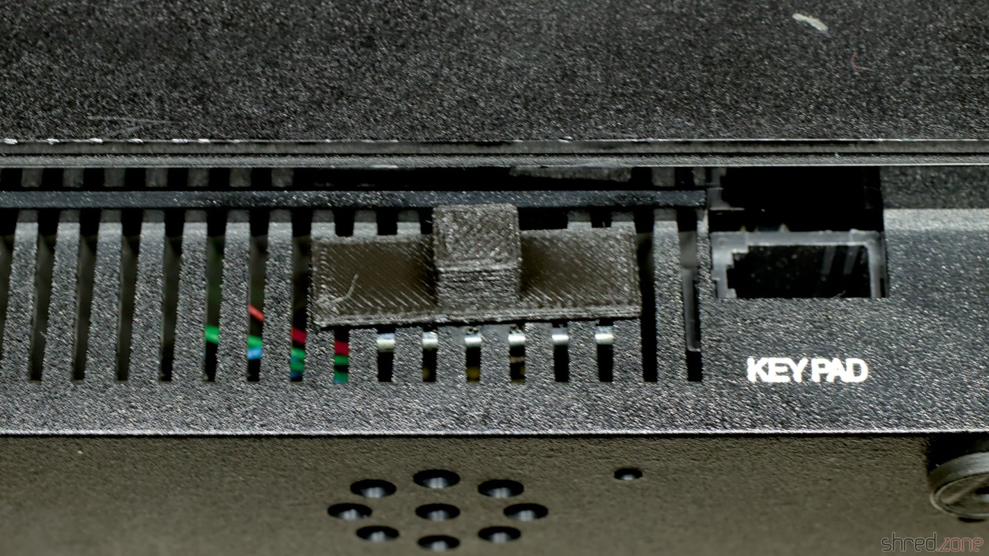
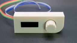
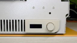
The modification must be fully reversible, and I also wanted to keep the original look of the Sidecar with its floppy drive. I designed a Gotek bracket for the expansion slot and a control panel with OLED display and encoder. The panel is screwed to the front air grille, so no holes need to be drilled into the case.

The Gotek bracket on the expansion slot. The control panel, ready for mounting. The control panel, mounted to the front of the case.

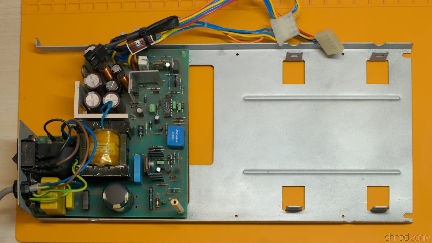
I made a new flat cable to connect the Gotek drive and the floppy drive to the mainboard. The Gotek drive is supposed to be drive A:, while the floppy drive should be B:. Both drives can be configured with jumpers, so there is no need to make a twisted floppy cable.

First Test Run

For the first test run I did not connect the Sidecar to the Amiga yet. If something on the Sidecar was badly broken, it wouldn't damage the Amiga that way.

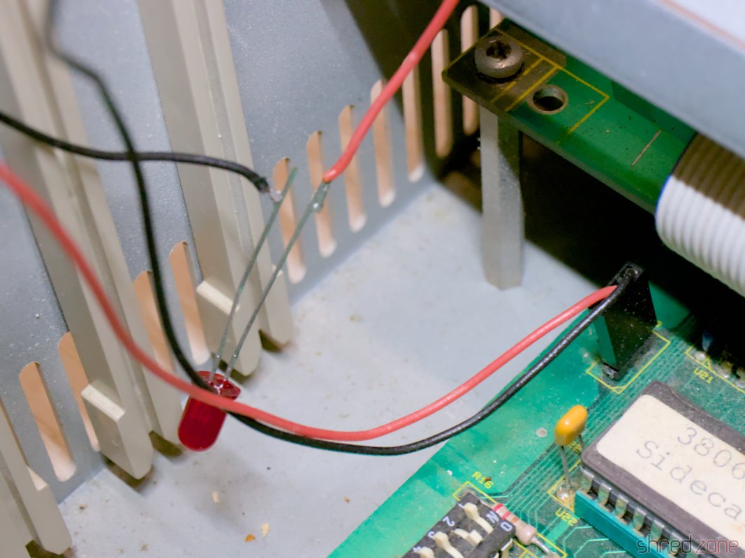
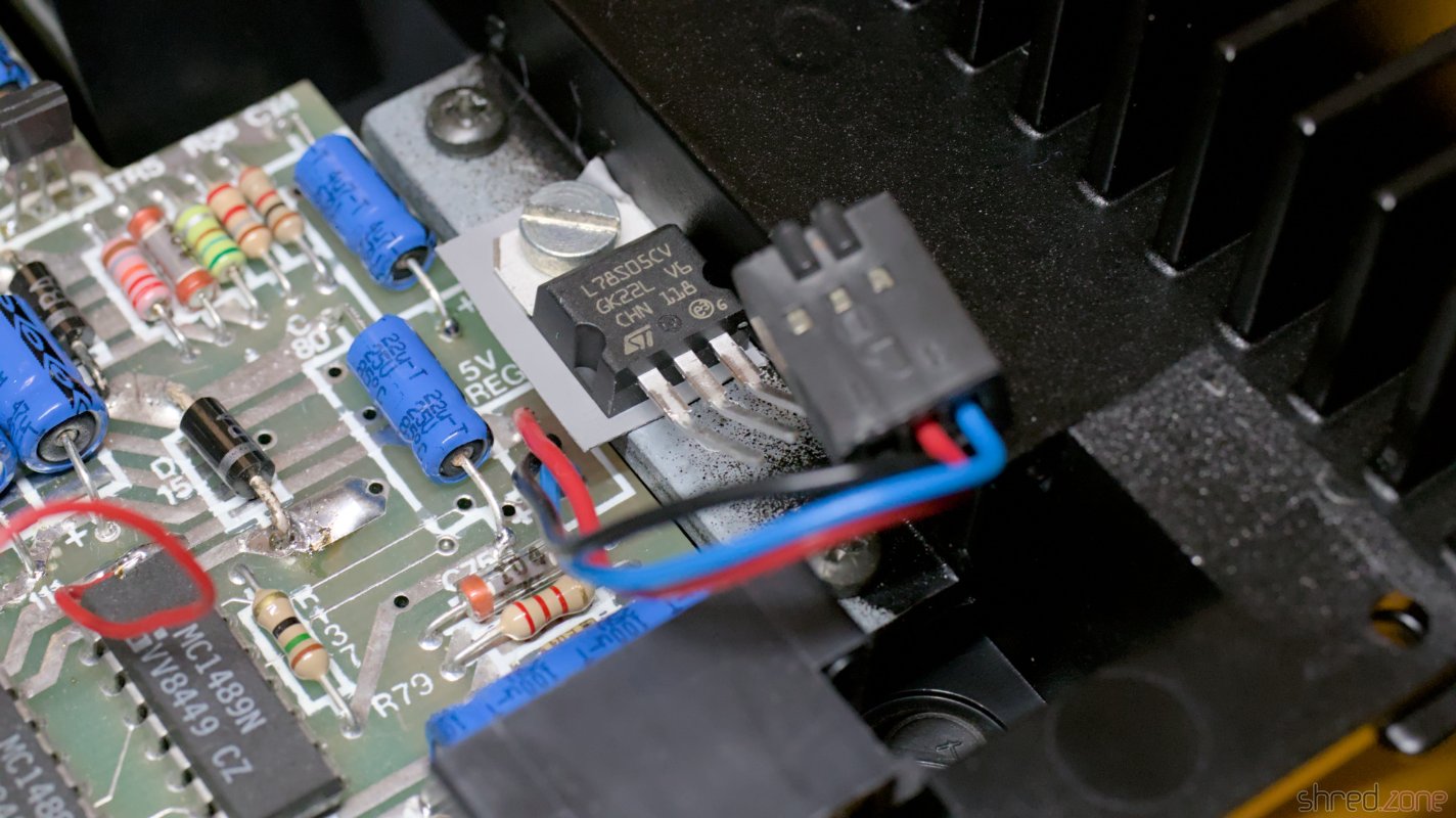
So I turned on the power. The fan spun up, the power LED lit up, but nothing else happened. Well, since the Sidecar is not meant to work as a standalone PC, this is probably normal. At least there was no magic smoke and no smell of smoldering electronics. I took the opportunity to check the voltages, and they were all correct and stable.

Things looked pretty good.

Making a Janus Workbench

The Sidecar is controlled by the Amiga. It has no connectors for a monitor or keyboard. Fortunately, the driver disk can still be found on the internet. For installation, I first had to make a copy of the original Workbench 1.2 disk, and then run the installer from the install disk.

On my Amiga 1000 however, the installation failed because the RAM disk ran out of memory. My Amiga is equipped with the maximum 512KB of Chip RAM, so it was supposed to work. I tried it multiple times, but always got this strange error.

I gave up and set up a UAE instance of an Amiga 500 with Kickstart 1.2 and 2 MB of Fast RAM. On this machine I was finally able to complete the installation.

The installer is a bit strange and not based on the Amiga installer tool that came later. It is best to use the default options and wait patiently for each step to complete.

Test Runs and Fixes

My test configuration, with the Amiga 1000 and the Sidecar. It takes a lot of space. It's finally time for a real test run.

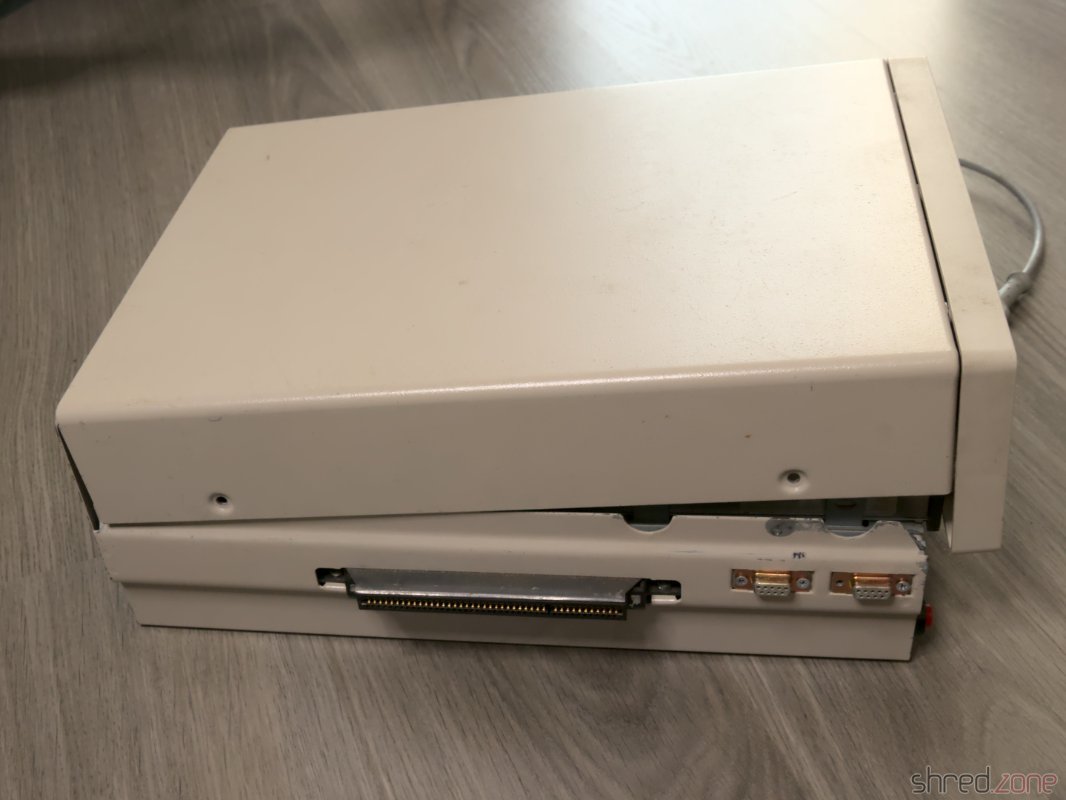
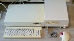
Connecting the two devices isn't easy and can damage the hardware if done wrong. First I unplugged the power cords from the Sidecar and the Amiga. Then I connected the Sidecar to the expansion port of the Amiga. It's a bit tricky to find the correct position, but the joystick and mouse connectors are a good orientation guide. There is no need to use force.

The Sidecar also has a power cord extender. I plugged it into the Amiga's power connector and made sure that the Amiga's power switch was turned on. Both devices can now be controlled with the power switch of the Sidecar.

CAUTION: You must never turn on power to the Sidecar unless the Amiga is already powered up. Otherwise you will damage your Amiga! You can avoid this problem by using the power cord extender and making sure that the Amiga's power switch is always on.

Now it was time for the truth. I booted the Janus Workbench I prepared above, but got a Guru Meditation during startup. I tried other driver versions and other floppy disk images I could find, but it always ended with the flashing red square.

Fortunately, the hardware registers are well described in the A500/A2000 Technical Reference Manual, Section 4.1. The description is for the A2088XT bridge board, but it is very similar to the Sidecar.

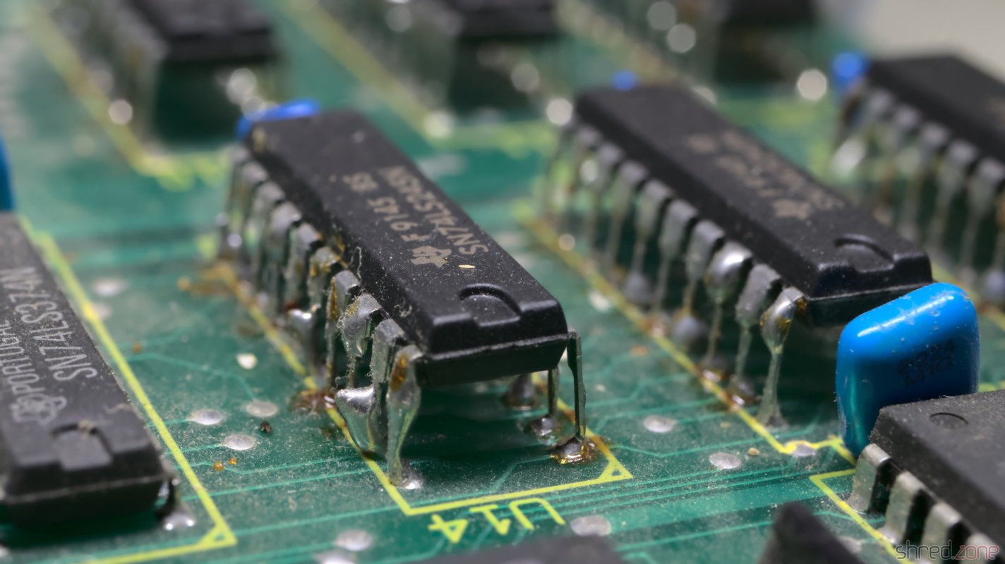
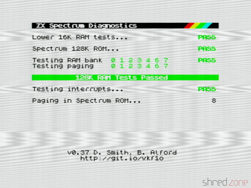
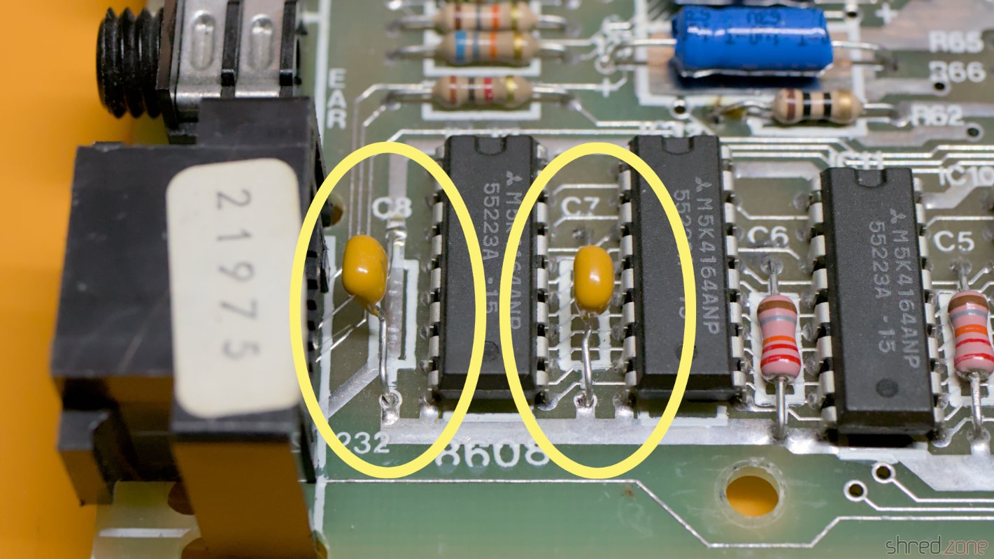
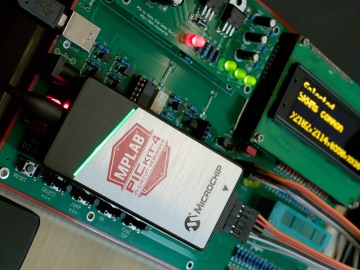
I quickly hacked some small diagnostic tools. They confirmed that the 128KB bridge RAM and the six replaced bus drivers were working fine.

I also found that the PC reset did not work. I only managed to actually reset the PC once. It played a chime and then actually accessed the MS-DOS disk I had in the Gotek drive. This means that the PC side was basically working, but the bridge board was having problems.

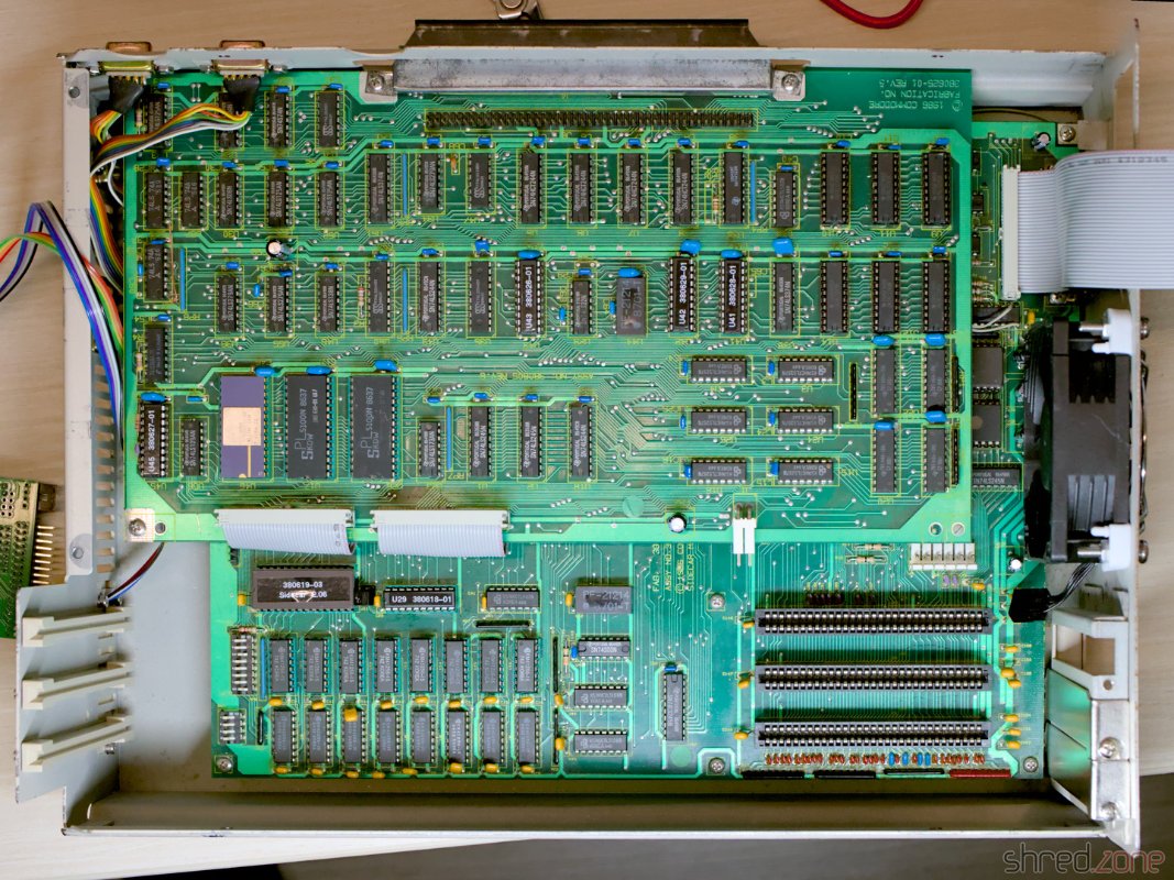
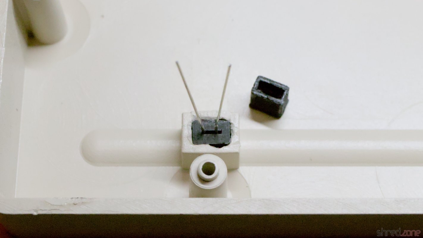
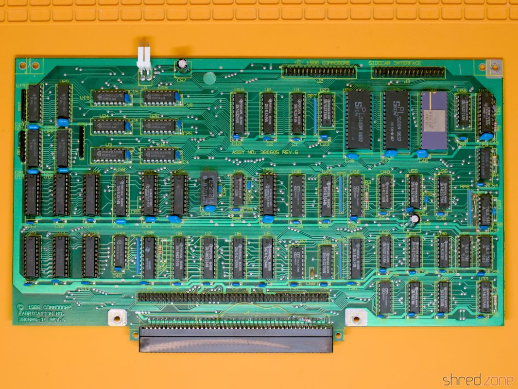
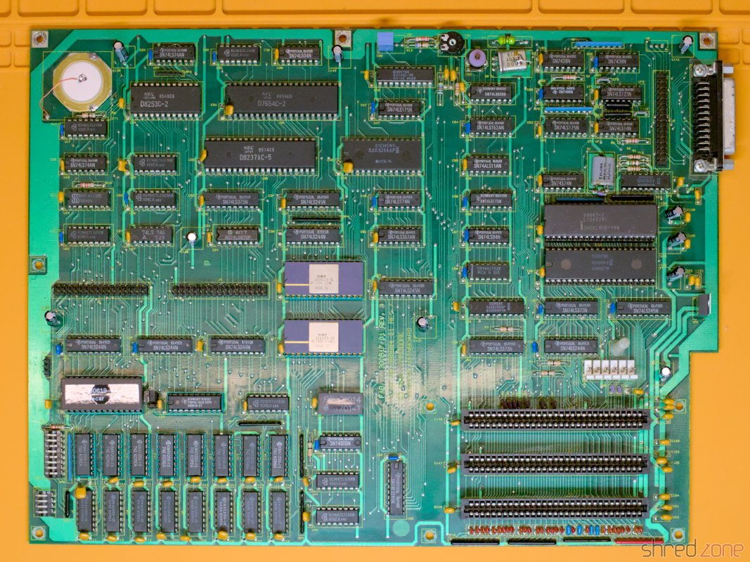
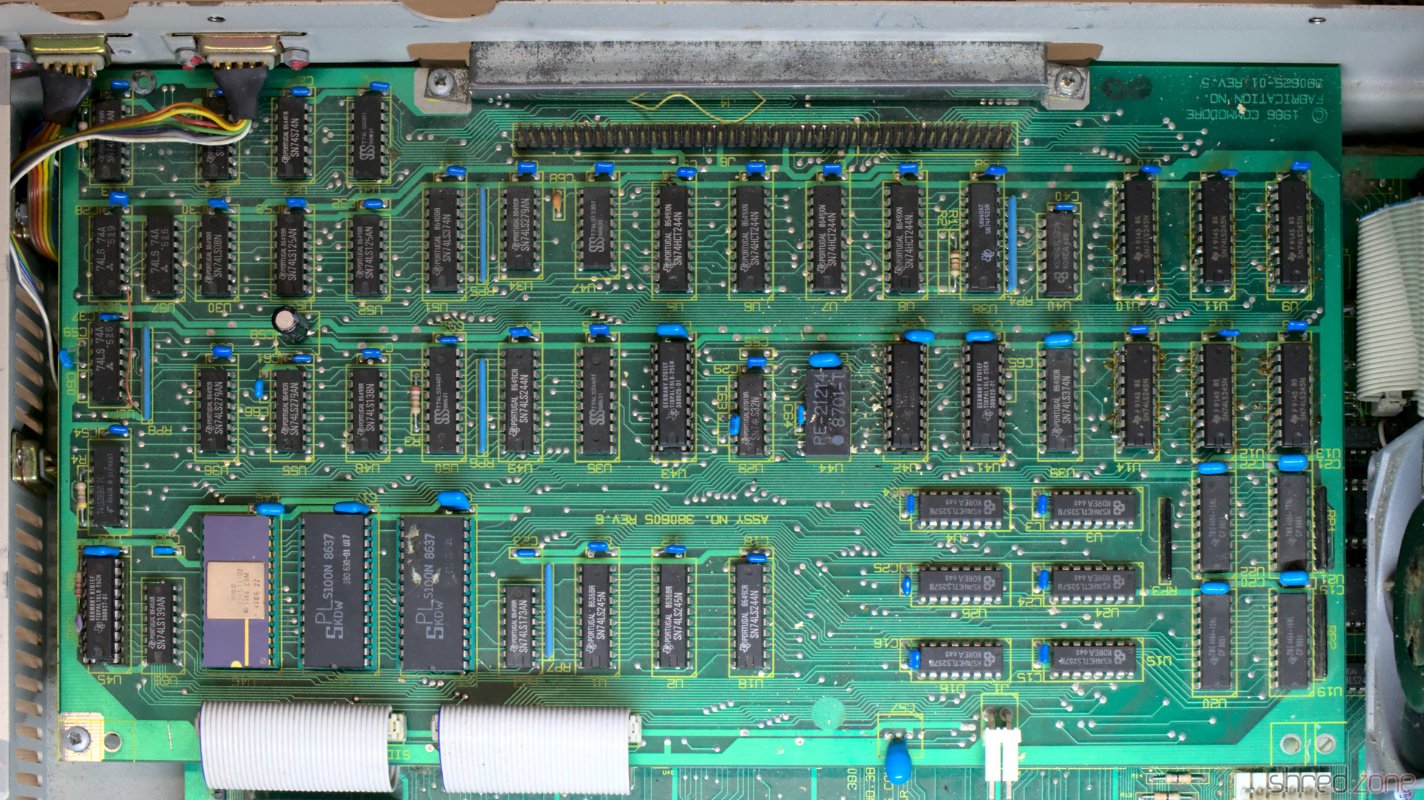
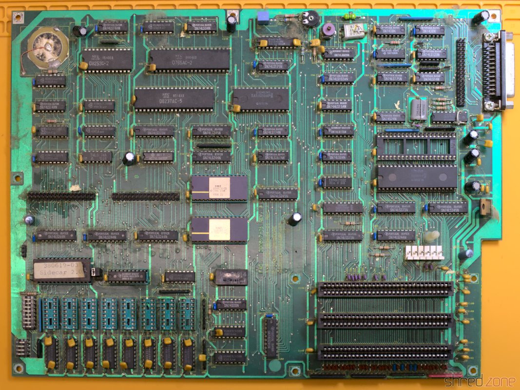
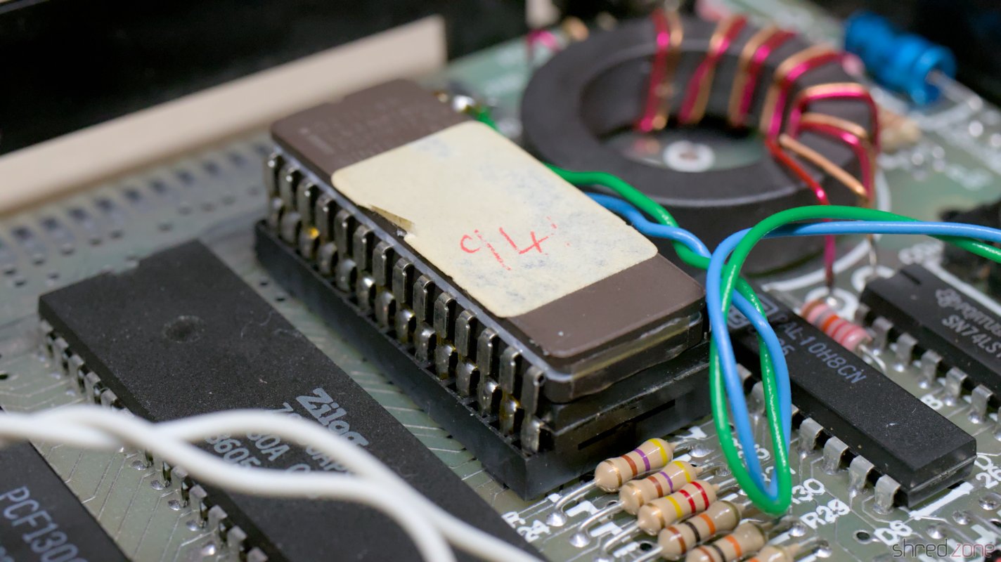
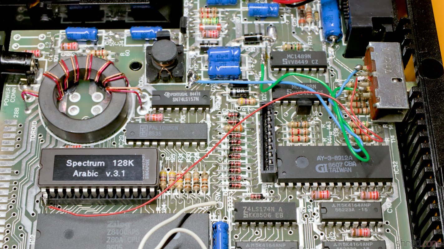
There are four PALs and three FPLAs on the upper board. The PALs have a specified memory retention time of about 20 years, which is long past. I remembered that the PALs on my MaestroPro were already having memory problems due to old age.

The fusemaps of the PALs can be found on the Amiga Wiki. I replaced the four PALs with modern ATF16V8C-7PU GALs.

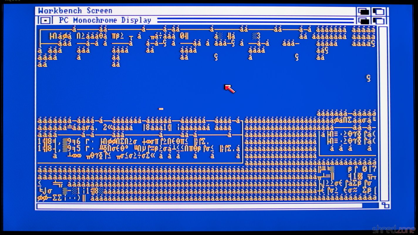
After that I was able to reset the machine reliably. The Guru Meditation was also gone when I booted the Janus Workbench. But the Sidecar still refused to come back out of retirement. What I got now was a garbled PC screen.

No Guru Meditation, but the screen content isn't good yet.

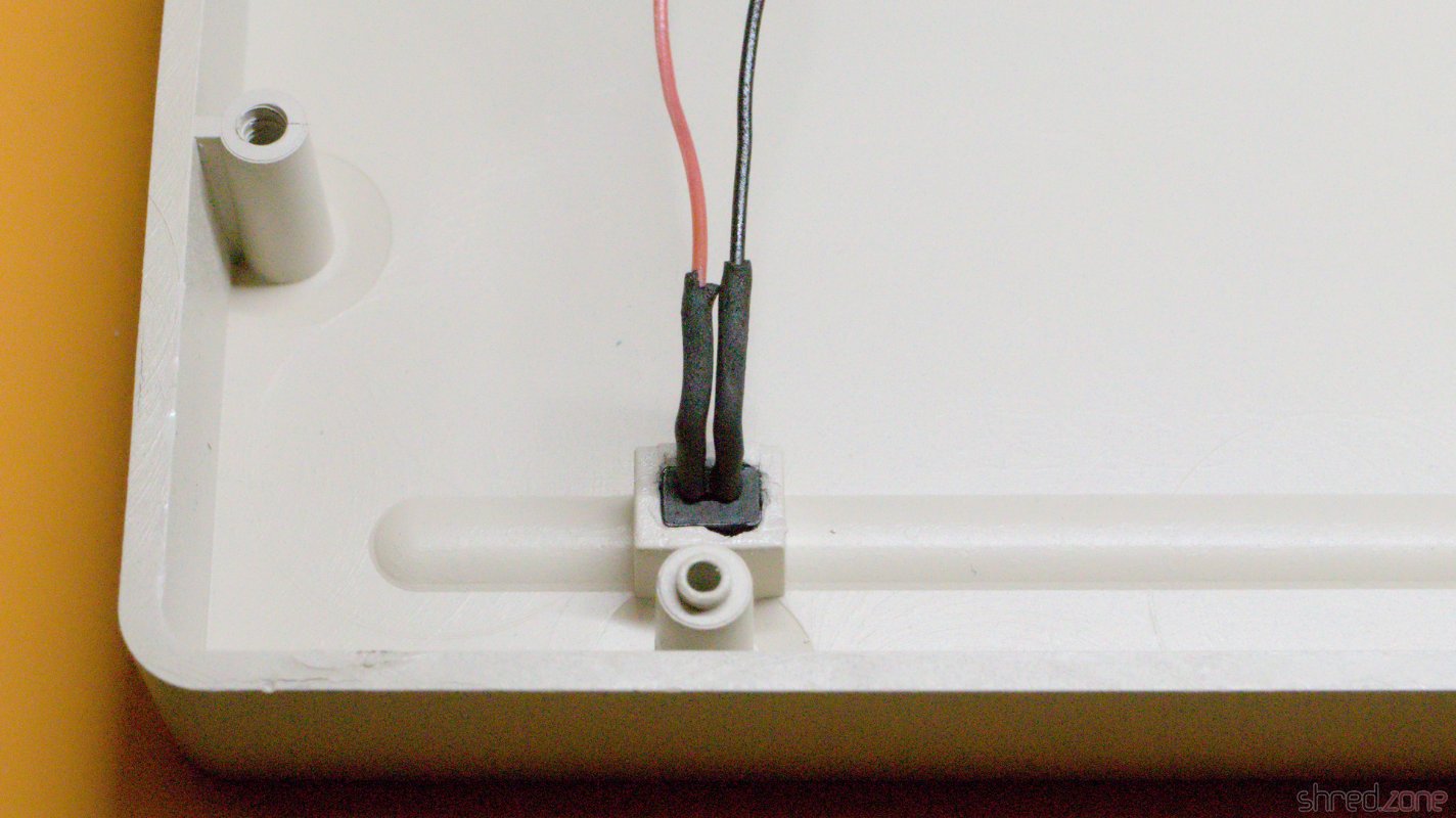
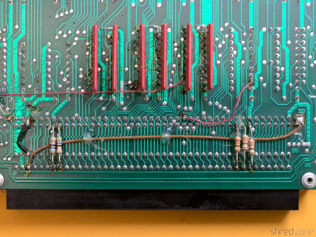
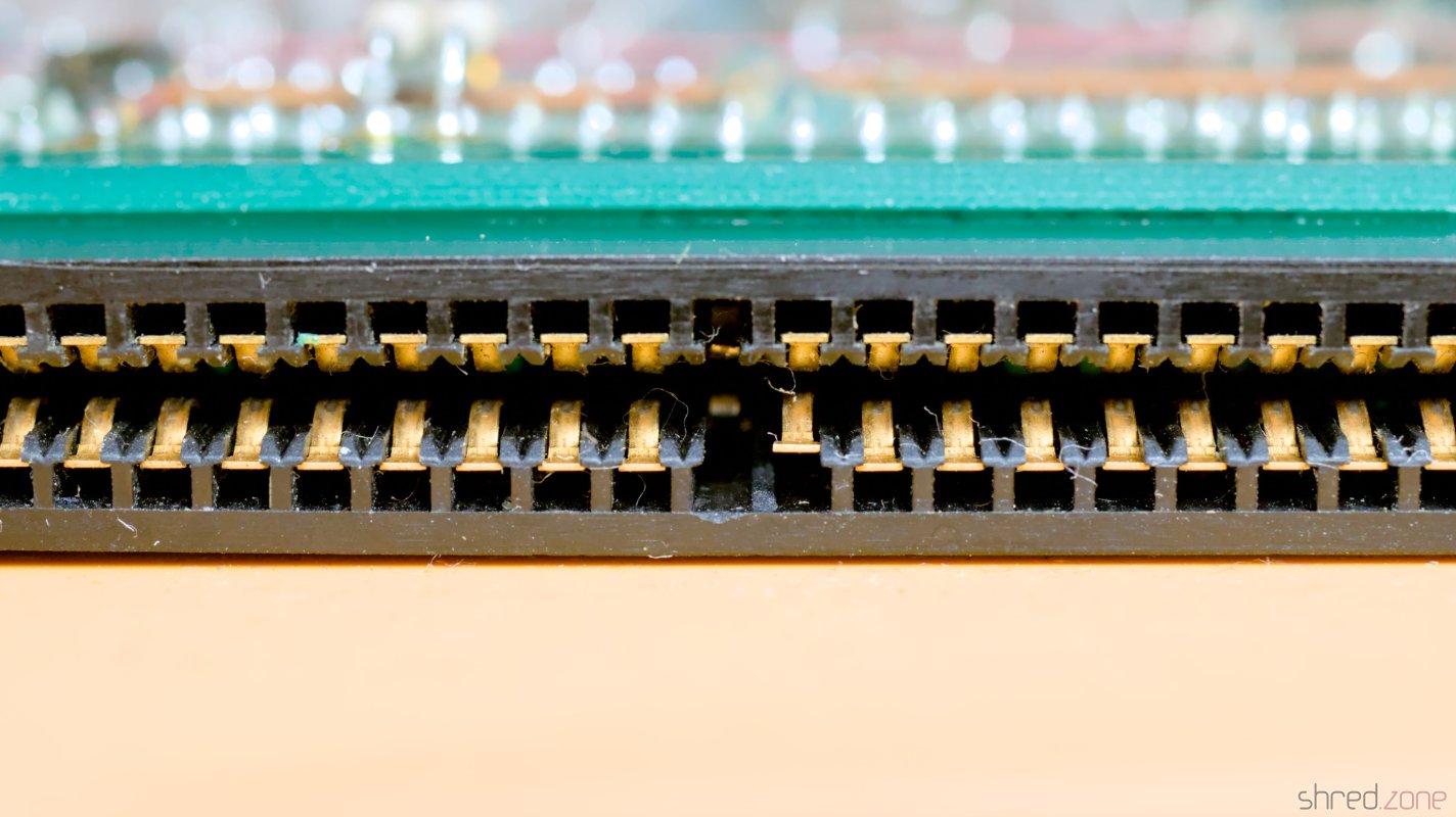
But I was on the right track! There is also a single PAL (and two FPLAs) on the lower board. I replaced this PAL as well, and also replaced the ribbon cables that are connecting both boards. The original cables still looked good, but the wires may have been damaged or corroded, and replacement is cheap.

The Sidecar with the replaced PALs and new cables.

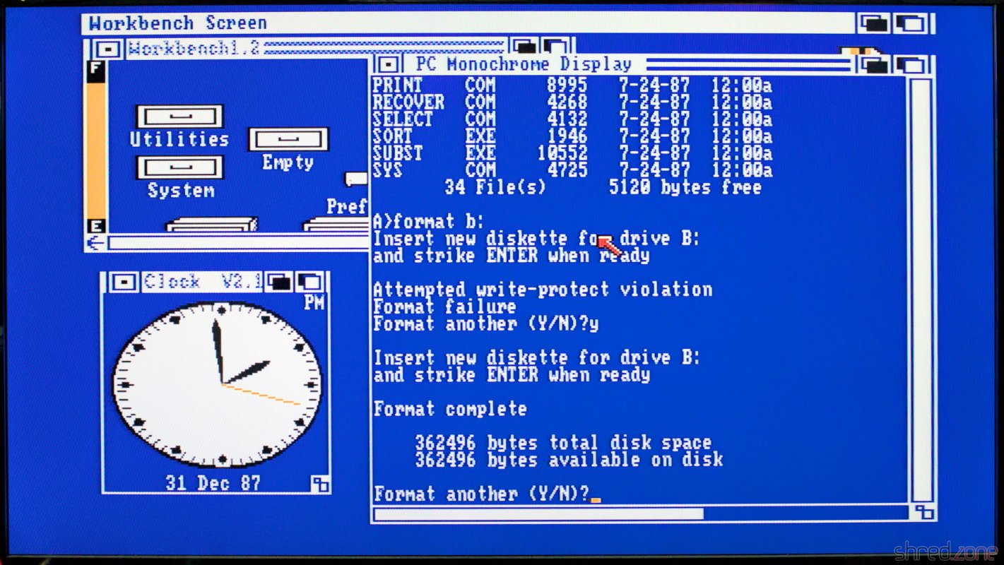
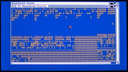
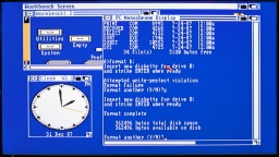
Next attempt. And finally, this time I was successful! I tested the machine for about an hour, formatted some floppy disks I bought somewhere, started Turbo Pascal. Everything worked reliably, and it was impressive to see MS-DOS running in one Amiga window and still have the full power of Amiga's multitasking to run Amiga software.

MS-DOS in one window, Amiga Workbench and Clock in other windows.

I was lucky. The PALs were easy to replace, as compatible GALs are still being produced today. The FPLAs can also potentially lose their programming, but there are no modern replacements. Mattis Lind designed a replacement board that uses a modern CPLD, but there are no corresponding JED files for programming them.

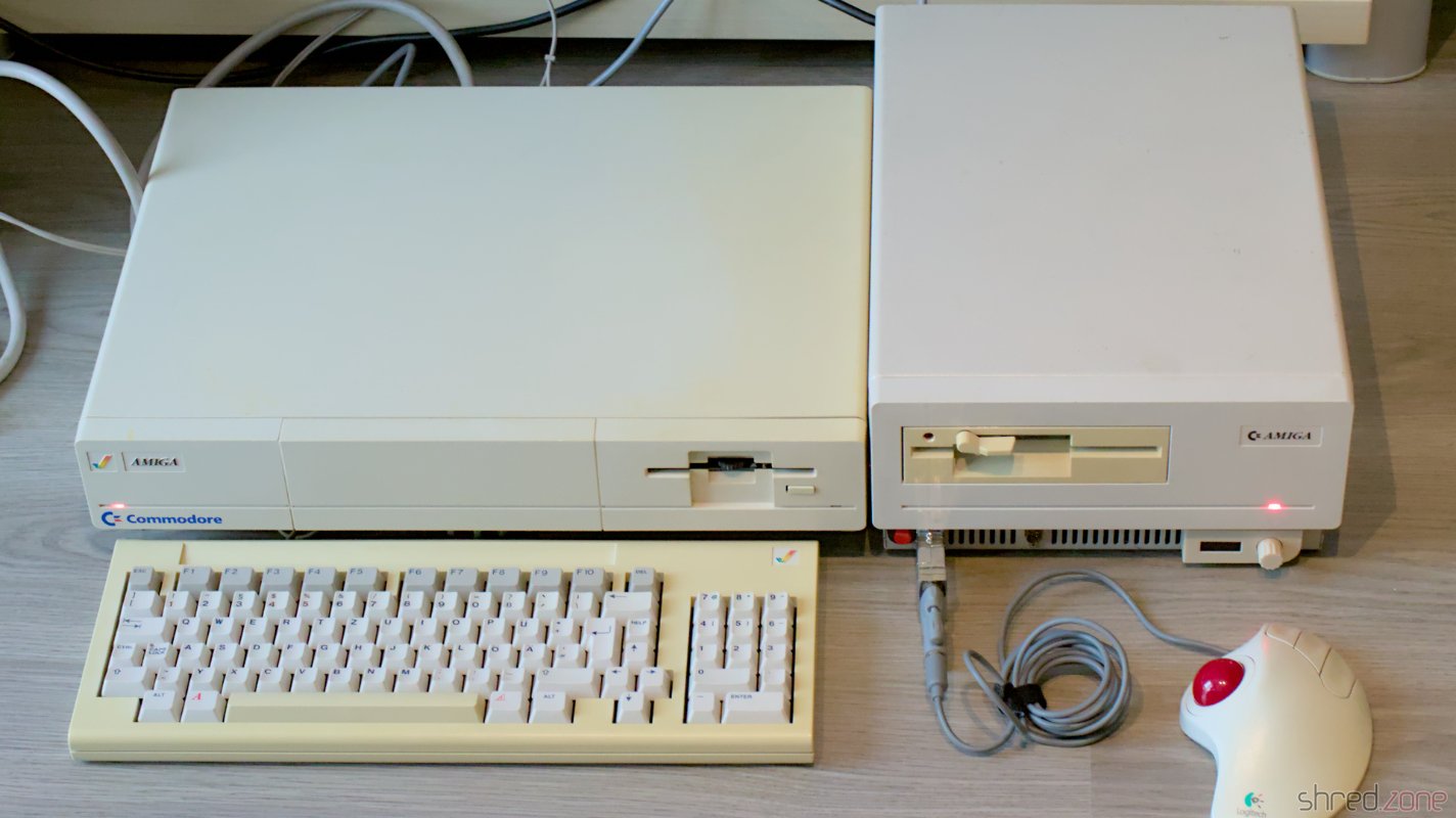
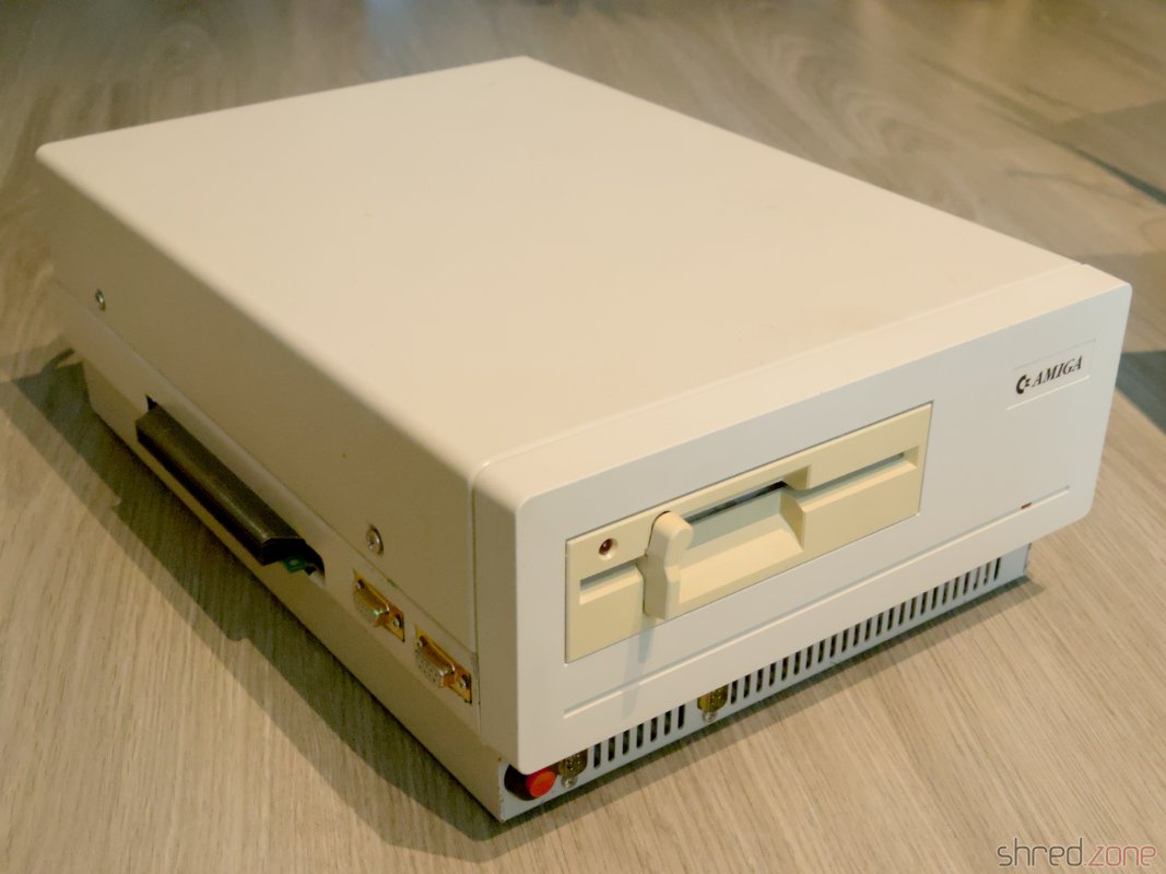
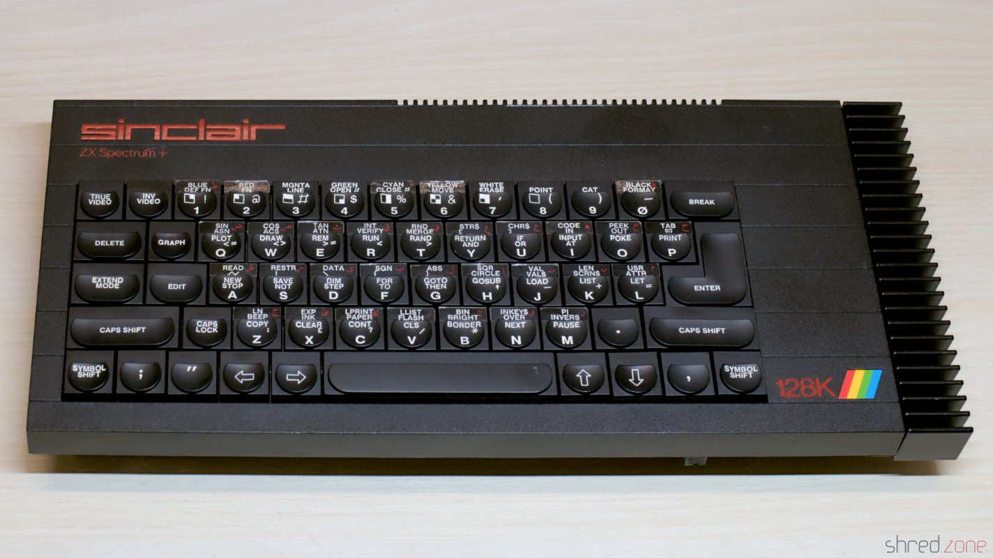
And there it is, my fully restored and futureproofed Commmodore A1060 Sidecar!

The Sidecar, fully restored, and with Gotek controller.

The restoration was much more difficult than I expected. There were many bad surprises waiting for me, and more than once I was close to giving up the project and storing the Sidecar away for later.

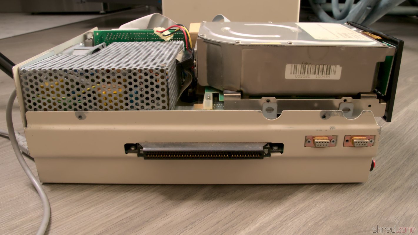
This beast is difficult to repair. First of all because of its size. The Amiga 1000 plus Sidecar was too big for the table in my tiny workshop, so I could not use my scope. Also there is not much use in running the Sidecar alone, so you always need a running Amiga 1000 for troubleshooting. Third, it's hard to find a place to put the Sidecar's PSU while probing the boards. The open nature of the PSU also poses a risk of electrocution if accidentally touched. All in all it was an interesting experience and I have learned a lot about Commodore bridgeboards in general and the Sidecar in special, but I probably wouldn't do it again.

Sidecar Restauration, Part 2

In the first part, I disassembled the Sidecar. In this second part, I will fix all the broken things and put the Sidecar back together in its original state.

Let's start with the mechanics. The floppy/PSU frame had some rust spots. I used a sanding machine to remove them all. Then I used zinc spray to protect the metal and restore the original look. The result was much better than expected. The frame now looks almost links new.

The PSU/floppy frame, coated with fresh zinc.

I got the overhauled PSU back. @DingensCGN, who already overhauled my Amiga 1000 PSU, did an excellent job again. He replaced all electrolytic capacitors and the power filter, removed the luster terminals and inserted a new pull relief. I also asked him to add a connector for a 12V fan. The original fan was a 230V model and was said to be awfully noisy. I never liked noisy computers, so I will replace it with a modern 80mm Noctua fan.

The overhauled PSU without the metal cage.

I'm always relieved to know that a power supply is safe to use, properly grounded, and won't damage the machine or electrocute me. 🙂

I was also lucky enough to find a Chinon FZ-502 at an online auction. This type of floppy drive type was commonly used in a Sidecar and would restore the original look of the front.

The PSU in its cage, and the new old floppy drive.

There is a metal shield supposed to be around the floppy drive, but unfortunately it was lost. It's not a required part though, and no one would notice it was missing once the case is closed.

Next problem: The legs of the power LED were broken off and the LED is stuck. I had no choice but to use brute force. I drilled out the LED and the plug that held it in place. I had to be very careful. If I drilled too deep, I would ruin the look of the front.

I then used a new standard rectangular red LED and 3D printed a plug to hold it in place without glue. The new LED is held firmly in place, but could still be removed by gently pushing it out from the front side with a screwdriver.

The LED is drilled out, fortunately without damaging the front. The new LED and the 3D printed plug. The replacement LED is ready to use.

The mechanical part is done. Time for the electronics.

On the upper board only a single electrolytic cap had to be replaced. But it took a lot of unsoldering work to remove the broken Zorro connector and the six bus driver chips. The original Zorro connector was held in place by two rivets, and I had no choice but to drill them out, slightly damaging the board in the process. I then washed the board thoroughly with IPA.

The upper board: cleaned, recapped, new Zorro connector, and the six driver chips seated in sockets.

There was also a tantalum capacitor, which I replaced with a new electrolytic one. This is not really necessary, but I don't trust old tantalums. They cannot leak like electrolytic ones, but they can catch fire or explode, causing even more damage to the board than electrolyte.

On the bottom board, there were ten electrolytic caps due for replacement. I also replaced the rusted piezo buzzer, which was a bit difficult because the new one turned out to be surprisingly sensitive to heat.

I don't like empty sockets, so I organized an 8087 FPU. Eight 41256 DRAM cells will upgrade the machine to the maximum possible 512 KB RAM. (The famous 640 KB can only be reached with a RAM expansion card.)

The installed Sidecar V2.06 firmware was the latest version I could find, so I just gave the original EPROM a new label, as the old one came off because the glue had dried out.

Lower board: Recapped, new piezo, new FPU, DRAM fully extended.

The board needs a new configuration after the change. Fortunately the original manual can still be found.

I also replaced all screws with new ones.

And finally, it's time for reassembly. Probably for the first time in decades, the Sidecar's case was closed again.

Lower board, back in the case. The reset line is reconnected. Floppy/PSU frame and upper board (below, not visible). The screws of the new fan are still missing. The restored Amiga 1060 "Sidecar".

Isn't she a beauty? 😍

That's all for the second part. If you've been following my article closely, you'll have noticed that I haven't turned on the machine yet. That's right. I avoid powering up old computers without at least having the PSU inspected, because there is a risk that (after decades of storage) the PSU is defective and could damage the machine or go up in smoke.

In the third and last part I will connect the Sidecar to my Amiga and finally find out if it works.

List of Capacitors

Lower board:

  • 2x 100µF 16V radial
  • 8x 47µF 25V radial

Upper board:

  • 1x 100µF 16V radial
  • 1x 47µF 25V radial (as replacement for the tantalum at C57)
Sidecar Restauration, Part 1

Front view of the A1060 Sidecar, but with a gaping hole where the floppy drive is supposed to be. I was lucky and got hand on a Commodore A1060 "Sidecar". This first part is about the teardown of the Sidecar, and the damage assessment.

But what is a Sidecar? When Commodore released the Amiga 1000, its graphics and sound capabilities were unmatched in that price range. However, because the machine was based on the Motorola 68000 processor, users were unable to run existing MS-DOS software on the machine.

The German Commodore factory in Braunschweig tried to solve this problem with the Amiga 1060. The machine was connected to the Amiga 1000 and provided a full IBM compatible PC. Although it was a standalone computer, it had no video and keyboard ports, but was fully controlled by the Amiga. Because it was connected to the right side of the Amiga, it looked like the sidecar of a motorcycle, which gave it its nickname.

The Sidecar came relatively late to the market, could only be used with the Amiga 1000, and was quite expensive. For this reason, only a small number were produced. I could not find any official figures, but according to Dr. Peter Kittel (an engineer at Commodore Braunschweig) only between 3,000 and 5,000 units were sold in Germany, and certainly even less worldwide.

My A1060 came with an open case top. The reason was that the 5¼" floppy drive had been removed, and a full-height hard disk drive had taken its place. It was so tall that it didn't fit in the case, and it was also surprisingly heavy.

The case cannot be closed for a reason. With the case top removed, there is a huge harddisk where the floppy drive is supposed to be.

Many screws were missing or oxidized, but otherwise the machine was in used but acceptable optical condition. The previous owner had added a reset button on the front, and a second D-Sub connector on the back (which later turned out to be a second floppy drive connector, for whatever reason).

I decided to take the entire machine apart for cleaning and damage assessment. My plans are to restore it to its original state, which also means removing the oversize hard drive and its controller board.

There is a frame that holds the floppy drive and PSU. I found a lot of strange rust on it, which looks a bit like moisture damage, but that wouldn't explain the shape of the stains.

A lot of rust stains on the floppy/PSU frame.

The PSU looked okay-ish. Luster terminals were used for the floppy power connector. Also the pull relief for the Amiga power cord was missing, instead I found a knot in the cord.

The PSU looks good, but the caps certainly need to be replaced. A knot as pull relief. Please don't try that at home!

I gave the PSU to an experienced technician at the a1k.org Amiga board for overhaul.

I also found that the pins of the power LED were broken off. The LED was held in place by a superglued plastic plug. It was impossible to remove without force. The replacement power LED was just hanging loosely in the case.

The power LED, with the legs broken off. I couldn't pull it out. The replacement LED.

Let's dig deeper. The computer consists of two boards. The lower board is the PC compatible, with three XT bus slots, a socket for the FPU, and eight sockets for another 256 KB of RAM. The upper board serves as a bridge between the Amiga and PC side. Both boards are connected by two flat ribbon cables.

At the first glance, the upper board looked dirty, but otherwise okay. On the bottom side there are a lot of bodge wires, additional resistors, and cut traces. At first I thought that this modification had been done by the previous owner, but then I found similar photos on the internet, so it seems to be a standard post-production factory fix.

The upper "bridge" board. The bottom side shows many hardware modifications.

Then I found that six 74HC245 bus drivers had been replaced with 74LS245 ones. The replacement was a little "creative". The old chips were cut off the board leg by leg, and the new chips were then soldered to the remains of the old legs. This was certainly not factory-made.

On the one hand, I was glad that the previous owner did not try to unsolder the chips, as he could have damaged the board. On the other hand, it looked very DIY, so I decided to clean up the mess later.

The driver chips, just soldered onto the board.

Replacing the 74HC245 with 74LS245 turned out to be a common fix to make the Sidecar more compatible with Amiga memory expansions. I decided to keep the 74LS245, but to use sockets so that it would be easy to undo this modification.

I also found that the Zorro connector was unfortunately damaged beyond repair. Two pins were broken off and another one was bent so it could cause a short.

Closeup of the damaged Zorro connector.

It was impossible to find a replacement 88-pin edge connector that could also be riveted to the board, but I did find a new connector of the correct size but without the rivet holes.

The lower board was even dirtier, but otherwise seemed to be unmodified and undamaged. The buzzer, however, was rusted, so I would have to replace it.

The lower "PC" board, dirty but otherwise okay.

In the end, there is a lot of work to be done:

  • Clean the case, remove the rust, replace all screws
  • Fix the power LED
  • PSU overhaul
  • Replacing all electrolytic caps, the buzzer, and the Zorro connector
  • Clean up the six bus drivers at the upper PCB
  • Find a new floppy drive

More of this in the second part of this article!

An Arabic Toast Rack

The Sinclair ZX Spectrum+ 128K "Toast Rack" This time, I have a true curiosity for you. 🙂

It's a ZX Spectrum 128K. It was designed by Sinclair and their Spanish distributor Investrónica, and was a major upgrade of the ZX Spectrum 48K. At that time, the 48K model was rather outdated with its limited RAM and the simple sound beeper, and Sinclair had nothing in its hand to compete with the Commodore 64 which was gaining ground in more and more households.

The 128K model has 128K of RAM (which also allowed double buffering), an AY-3-8912 sound chip, an RGB monitor port, a serial port and an optional external numerical keypad. Hardware sprites are still missing though. On software side, it provides a heavily improved BASIC.

The shape of the prominent heat sink on the right side of the case gave the machine its nickname: "Toast Rack".

The model was first sold in Spain, as Sinclair UK still had a large number of unsold 48K models. In the end it could not save Sinclair from bankruptcy, but the 128K model was certainly very attractive for the new owner Amstrad. Today, the Toast Rack is a sought-after item for any serious Sinclair collector.

What makes this special model so curious is that it is an Arabic modification. 😀 There are stickers with Arabic letters on the keyboard, and at the front side there is a switch to select between the original 128K ROM and an Arabic version of the 48K ROM.

The stickers with Arabic letters on the keyboard. The front side with the switch, and a hand-written inscript "A gift of the Alumni Association".

My first thought was that this was an elaborate DIY modification. But then I found a thread in a Sinclair forum. It says that Matsico, a Sinclair/Amstrad agency in Egypt, has produced these models. I could not find more information about it though, so I don't know if they were actually sold, or just made as a proof-of-concept or promotional gift.

What they all have in common, is the switch at the front, and an EPROM soldered on top of the ROM. The only known exception I found in a video by ByteDelight about a ZX Spectrum +3, where the ROM could be selected via a separate boot menu.

Inside is an Issue 6U board. The EPROM with the Arabic version is soldered on top of the original ROM, presumably for license reasons.

Restoration

A first diagnostics run showed that the board was working fine. The only issues were massive picture interferences, and an almost inaudible sound from the AY chip.

Both issues are known problems with that model. A blog article by Adam's Vintage Computer Restorations addresses them.

First of all, I replaced all electrolytic capacitors with premium ones. I'm doing that with all retro machines, irregarding their age and rareness. However I try my best to maintain the "retro optics", for example by using axial caps in that classic blue color.

To enhance the image quality, I used a 47µF electrolytic cap for C28 (original was 22µF), and replaced C7 and C8 with 1µF MLCCs. I could also rewire C126 as mentioned in the blog article, to enhance image quality even further, but I decided to postpone that.

C7 and C8 replaced with 1µF MLCCs. Unfortunately I could not source axial ones. C28 replaced with 47µF.

To raise the volume of the AY sound chip (so it has a similar level as the beeper), I replaced R115 with a 1.65kΩ resistor.

R115 replaced with 1.65kΩ.

The 7805 voltage regulator is rated at 1A, and is working at its load limit on the 128K. This is the reason for the big heat sink on the right side. I replaced it with an 78S05, which is a drop-in replacement that is rated at 2A and stays considerably cooler.

I was lucky here, because in the past, someone had already replaced the 7805 with a LM1085. It is rated at 3A, but has a different pin configuration. If I had replaced it blindly, it would have killed the machine. You should always be prepared for nasty surprises when restoring old machines the previous owner already tinkered with!

The new 78S05 and a silicone heat conductor. Attention: The order of the wires has been arranged for the LM1085, the connector cannot be used like that for the 78S05!

I also cleaned the case (although it was already in a very clean state). The previous owner had already replaced the keyboard membrane, but the extra keys were not working there, so I replaced it with a new membrane of a known-good brand.

The machine, recapped and modified.

The next diagnostics run showed that all tests were still green. Also the picture interferences were mostly gone (except of some minimal jailbars that I can live with), and the AY sound is much louder.

Depending on the position of the switch, the system either boots into the original ZX Spectrum 128K startup menu, or shows an Arabic boot prompt. In the Arabic version, the entire BASIC has been modified, with all texts in Arabic and written from right to left. Unfortunately I cannot read it.

The original ZX Spectrum 128K boot menu. The boot prompt of the Arabic version: "Presented by Matsico Company, Sinclair/Amstrad agency of Egypt. Prepared by Nabil Nazmi."

A short test with the Dandanator module also showed that games are working fine. The mandatory part of the restoration is completed!

Screenshot of Cybernoid II.

Freestyle Restoration

There were two more things I didn't like.

First was the ROM stack. The original solution switched the Vcc pins of the ROMs, so one of the chips was always powerless, but still connected to the address and data bus. To be honest, I wonder why this was working at all.

Anyway, I replaced it with a single 27C512 EPROM. On the bottom half of the memory, I burned the Arabic ROM (twice), and on the upper half, I burned the original 128K ROM. After that, I modified the switch to pull the A15 address line (pin 1) either to GND or Vcc. This way, the EPROM is always powered and the desired operating system is selected by an address line. I also upgraded the original Arabic ROM version 1 to the latest version 3.1 I could find on the web.

Of course I will keep the ROM stack. Mainly for licensing reasons, but also so that the original solution can be restored if desired.

New single-EPROM solution.

I also didn't like the optics of the naked switch at the front, so I 3D-printed a small switch cap that also covers the screws.

There are a few more things that could be done:

  • I could also rewire C126 (as mentioned in Adam's blog article above), to remove the sound signal from the RGB output.
  • Due to a bug in the original PAL10H8, the system crashes just by reading the $7FFD port address. There is a fix that also removes a "rain" effect caused by refresh data on the bus.
  • The original ULA can be replaced with a vLA128, as a replacement if broken, or if the precious original part should be conserved.
  • Dave Curran reverse engineered the numeric keypad. An ambitious tinkerer could make a DIY keypad replica.
Competition Pro Mini refurbishment

I recently got two Competition Pro Mini joysticks. The full-size Competition Pro was probably one of the most famous joysticks back in the 1980s and early 1990s. This model was said to be unbreakable, and was able to withstand even long and intensive gaming sessions. If one of the microswitches eventually failed, it was easy to get a new one from an electronics store and replace it just by using a screwdriver, no soldering required.

The Mini models came to the market in 1992, and were by far not that robust. My two examples had broken microswitches at the left direction. The microswitches are soldered to the PCB, and they are also out of production.

The closest available replacement is the Saia-Burgess F4T7UL and F4T7GPUL (the latter one with gold-plated contacts). Unfortunately it has different solder tails, so it cannot be used as a drop-in replacment.

Left: The original microswitch. Right: The Saia-Burgess F4T7GPUL, with shorter solder tails.

I decided to build up a completely new PCB by InsaneDruid instead. It is a replica board with exactly the same size and fuctionality, but it is prepared to use the Saia-Burgess switches.

Auto-fire Model

The first thing I did was to completely disassemble the joystick. All plastic parts were cleaned in an ultrasonic bath. Meanwhile I noted the color order of the wires before cutting the cable from the old board.

The individual parts of the joystick.

The new board only needs very few components. Except of the switches, all of them are standard ones that can be found in any electronic store. The switches can be found at distributors like Mouser.

The replica PCB and all required components.

For the four directions, I first mounted the microswitches to the holder frame. This way it will be easier to perfectly align the switches to the PCB.

For the fire buttons, the middle solder tail needs to be cut off. Otherwise it will collide with a peg of the bottom case shell later.

The four directional switches are mounted to the frame using the four shorter original screws. Check the correct position of the plungers, and make sure the switches are lying flush to the frame. For the two fire buttons, the middle solder tails need to be cut off. It would collide with a peg of the bottom shell.

Usually we would start with the flattest component, but in this case, I recommend to start with the four direction switches. Position them to the frame so the four screws are perfectly aligned with the corresponding PCB holes. Make sure that the two LED holes are aligned to the "up" direction. Then start soldering the switches to the PCB, using a generous amount of solder.

Additionally you can use wire brackets to secure the switches using the provided mounting holes. I was too lazy to do that though.

The four switches are soldered to the upper side of the PCB. You can use wire brackets for additional securing. The bottom side, with the four screw heads centered in their PCB holes.

The remaining components are just soldered to the board. Finally the original cable is wired to the board, with the original order of wire colors.

The completed joystick board.

After that, the joystick is ready for reassembly.

Standard Model

My other joystick is a standard model without auto-fire function. Again, I disassembled it. All plastic parts were cleaned, while I noted down the color order of the wires.

The standard model, disassembled (before cleaning).

The cable of this model does not provide a +5V supply. For this reason, there is no need to populate the components for the auto-fire. We can also save the LEDs, as they won't light up.

The standard model needs considerably less components: Just six switches, and a short piece of wire.

The preparation is the same as for the other joystick. The four direction switches are mounted to the frame, and the two fire switches lose their middle solder tail. After that, the frame with the switches is aligned and soldered to the board, followed by the fire switches.

We do not need to populate the mode switch. However, we need to solder in a wire bridge to pins 5 and 7 (see photo), otherwise the fire buttons won't work at all.

Bridge pins 5 and 7 with the wire.

The wires need a different order. On the original board, the "fire" signal is at the third position from the right (the orange wire on my joystick). On the new board, that signal is on the very right pad. The one left from it stays empty. For the remaining wires, the original order can be kept.

The original wiring. Your colors may be different. The wiring of the new board, with the orange wire to the right.

After that, this board is completed as well, and the joystick can be reassembled.

The completed standard joystick board.

The joysticks look as good as new now, with their clean case and their brand new boards.

The refurbished transparent green and transparent white Competition Pro Minis.

The ENIG plated PCBs are a true eye-catcher in their transparent cases.